Settings for connecting with the remote cameras and switcher (continued)

3.Turn the F2 dial to select “Yes”, and then press the F2 dial.

Auto IP setting starts.

During auto IP setting, the progress is indicated by the number of

” which are reduced one by one.

1.AUTO SET

   

When all the operations have been completed successfully, the following message appears.

1.AUTO SET

COMPLETE

The remote cameras and the switcher are automatically rebooted, and they restart with the new IP addresses which were set.

The remote cameras can now be operated from the unit.

The function for linking the switcher with the unit can now be used.

zzWhen setting the IP addresses failed, the following message appears.

1.AUTO SET

SET UP ERR!

The cause of the problem is likely to be a network malfunction. Check the connection status of the hub and LAN cables, and then retry the auto IP setting operation.

„„Leaving the IP addresses of the additional devices to be introduced unchanged and automatically updating the connection destination IP addresses set on the unit

<Overview of operation>

The link settings can be configured by executing “KEEP IP ADR” in AUTO IP menu [37].

With “KEEP IP ADR”, the unit first searches within the same subnet mask.

Then, links are set between the newly detected remote cameras and camera numbers for which the connection type is set to “NoAsign” on the unit.

At that time, the IP addresses of the remote cameras are kept as is and the connection destination IP address values set on the unit are overwritten.

Likewise, when a new switcher is detected while the connection type for the switcher is set to “NoAsign” on the unit, the link setting is configured by keeping the IP address of the detected switcher and overwriting the connection destination IP address value set on the unit.

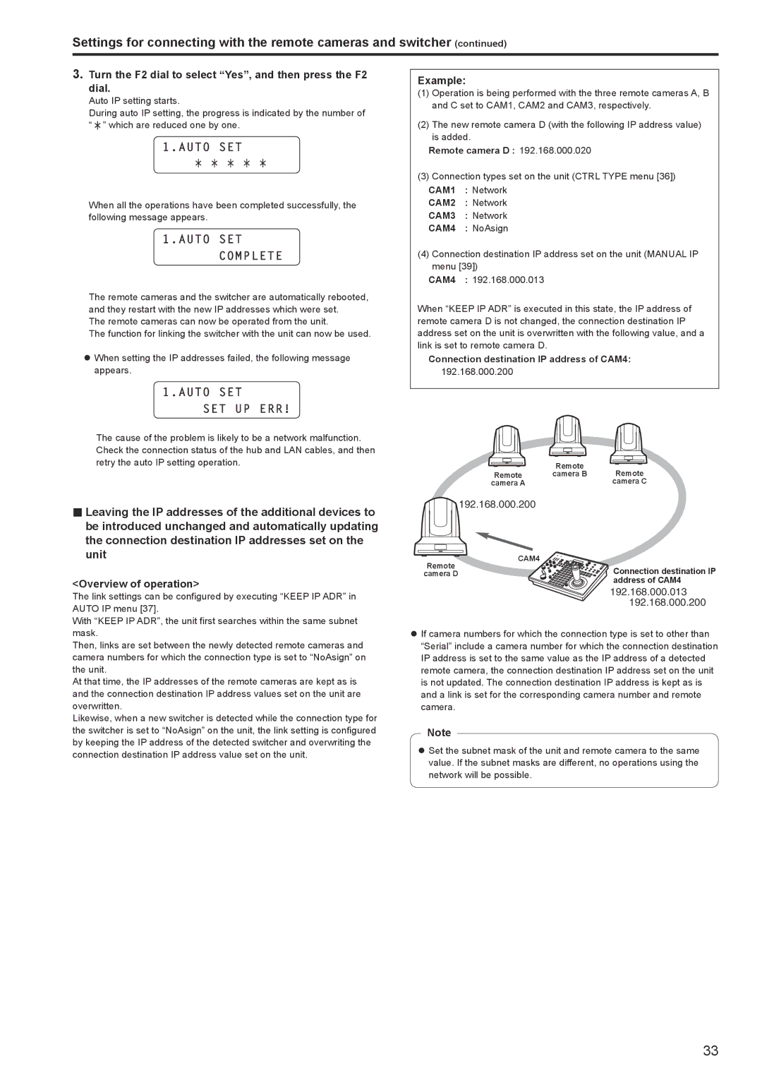
Example:

(1)Operation is being performed with the three remote cameras A, B and C set to CAM1, CAM2 and CAM3, respectively.

(2)The new remote camera D (with the following IP address value) is added.

Remote camera D : 192.168.000.020

(3)Connection types set on the unit (CTRL TYPE menu [36]) CAM1 : Network

CAM2 : Network

CAM3 : Network

CAM4 : NoAsign

(4)Connection destination IP address set on the unit (MANUAL IP menu [39])

CAM4 : 192.168.000.013

When “KEEP IP ADR” is executed in this state, the IP address of remote camera D is not changed, the connection destination IP address set on the unit is overwritten with the following value, and a link is set to remote camera D.

Connection destination IP address of CAM4:

192.168.000.200


Remote

Remote

Remote

camera B

camera A


camera C

192.168.000.200

Remote

CAM4

Connection destination IP

camera D


address of CAM4

192.168.000.013 192.168.000.200

zzIf camera numbers for which the connection type is set to other than “Serial” include a camera number for which the connection destination IP address is set to the same value as the IP address of a detected remote camera, the connection destination IP address set on the unit is not updated. The connection destination IP address is kept as is and a link is set for the corresponding camera number and remote camera.

Note

zzSet the subnet mask of the unit and remote camera to the same value. If the subnet masks are different, no operations using the network will be possible.

33

Page 33
Image 33
Panasonic AW-RP120G Turn the F2 dial to select Yes, and then press the F2 dial, Connection destination IP address of CAM4

AW-RP120G specifications

The Panasonic AW-RP120G is a sophisticated remote camera controller designed for broadcasting and production environments that require precise control over multiple pan-tilt-zoom (PTZ) cameras. This versatile controller offers an extensive range of features, making it a reliable choice for professionals in the field.

One of the key highlights of the AW-RP120G is its user-friendly interface. It incorporates a large, LCD touchscreen display that provides real-time information and control options for both novice and experienced operators. The layout is intuitive, enabling quick access to various settings without the need for complex configurations. This allows operators to focus on their production rather than getting mired in technical details.

The AW-RP120G is equipped with the capability to control up to 200 PTZ cameras simultaneously, which caters to large-scale productions. This flexibility is crucial in various settings, from live events to studio broadcasts, where multiple camera angles and shots are necessary. The controller utilizes IP connectivity and supports the Panasonic’s proprietary protocol, ensuring seamless operation across a networked environment.

Another standout characteristic of the AW-RP120G is its advanced preset management system. Users can store and recall up to 100 preset camera positions, eliminating the need to manually adjust each PTZ camera during a live performance. This feature significantly enhances workflow efficiency and allows for smooth transitions between camera angles.

The device further incorporates advanced technologies, such as PoE (Power over Ethernet) compatibility, which simplifies installation by allowing power and data to be transmitted over a single cable. This reduces clutter and streamlines setup processes, particularly in complex environments.

In terms of design, the AW-RP120G is compact and portable, making it easy to integrate into various production setups. It is built with durability in mind, ensuring that it can withstand the rigors of frequent use in demanding environments.

Overall, the Panasonic AW-RP120G is a state-of-the-art remote controller that combines functionality, efficiency, and reliability. With its advanced features, it is an essential tool for any professional looking to elevate their camera operation capabilities in broadcasting and live event production. This makes it a valuable investment for those looking to enhance their production quality while streamlining their workflow.