CF-74ECBGDBM specifications
The Panasonic CF-74ECBGDBM is a rugged laptop designed to cater to the demanding needs of professionals who work in challenging environments. Built with durability as a top priority, this device serves as an ideal solution for industries such as public safety, construction, and field service.One of the standout features of the CF-74ECBGDBM is its rugged design. The laptop is compliant with military standards, specifically MIL-STD-810G, ensuring it can withstand harsh conditions. This includes resistance to drops, vibration, dust, and moisture, allowing users to operate it in rain or shine without fear of damage. The spill-resistant keyboard adds another layer of protection, making it suitable for environments where liquids are prevalent.
In terms of performance, the CF-74ECBGDBM is equipped with a powerful processor, which provides efficient multitasking capabilities. The device typically features an Intel Core i5 processor, enabling smooth operation of demanding applications. Coupled with a sufficient amount of RAM, users can expect enhanced speed and productivity, even when running multiple programs simultaneously.
The laptop features a sunlight-readable display, which ensures visibility in bright outdoor conditions. The screen is designed to reduce glare, making it user-friendly for professionals who work outside regularly. Additionally, the display is supported by a durable touchscreen option, allowing for easier navigation in various working conditions.
Storage is another critical aspect of the CF-74ECBGDBM, as it often comes with solid-state drive options that not only provide ample memory for files and applications but also enhance the overall speed and reliability of the system. Users can rely on fast read and write speeds, which are essential for data-heavy tasks.
Connectivity options are abundant on this device, featuring USB 3.0 ports, HDMI output, and options for mobile broadband. This allows users to connect various peripherals or external displays easily, as well as maintain seamless internet access on the go.
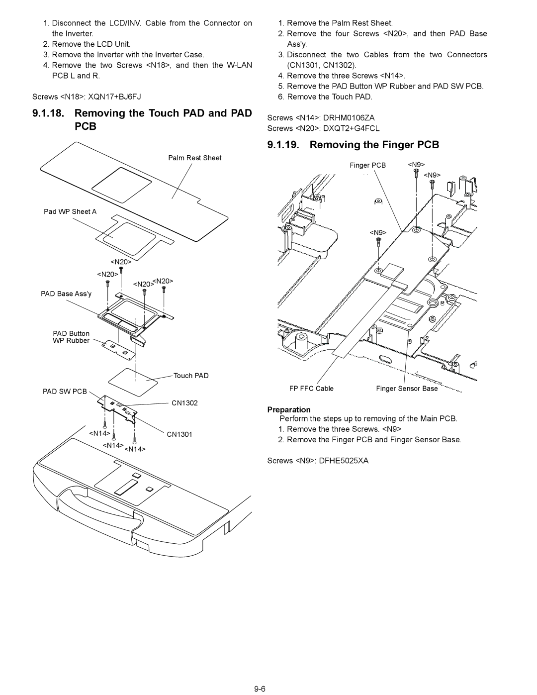
Furthermore, the CF-74ECBGDBM is equipped with a long-lasting battery that supports extended periods of use, ideal for professionals who spend time away from traditional power sources. The device is designed for easy serviceability, facilitating upgrades and repairs, which enhances its lifespan in demanding workplaces.
Overall, the Panasonic CF-74ECBGDBM stands out as a robust and versatile laptop that meets the needs of users in tough outdoor and industrial settings, making it a reliable companion for professionals on the move.

