(R) (Red)
(L) (White)
Cautions:
¡Check the connectors provided on your car (see precaution below) before connecting the system.
¡This unit is designed for use in a car having a
¡To prevent damage to the unit, be sure to follow the connection diagram. ¡Strip about 5 mm of the lead ends for connection (only
tor cords).
¡Do not insert the power connector into the unit until the wiring is com- pleted.
¡Be sure to insulate any exposed wires to prevent short circuiting with the car chassis. Bundle all cables, and prevent cable terminals from touch- ing any metal parts.
E
N
G
L
I
S
H
32
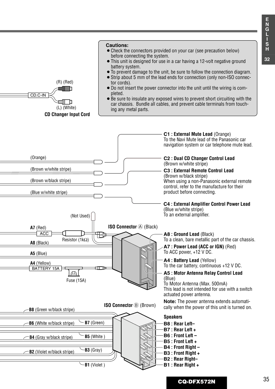
CD Changer Input Cord
C1 : External Mute Lead (Orange)
To the Navi Mute lead of the Panasonic car navigation system or car telephone mute lead.
(Orange) | C2 : Dual CD Changer Control Lead |
| (Brown w/white stripe) |
(Brown w/white stripe)
(Brown w/black stripe) (Blue w/white stripe)
|
| (Not Used) |
A7 | (Red) | ISO Connector A (Black) |
| ACC |
|
A8 | (Black) | Resistor (1kΩ) |
| ||
A5 | (Blue) |
|
A4 (Yellow)
BATTERY 15A
Fuse (15A)
ISO Connector B (Brown)
![]() B8 (Green w/black stripe)
B8 (Green w/black stripe)
C3 : External Remote Control Lead (Brown w/black stripe)
When using a
C4 : External Amplifier Control Power Lead (Blue w/white stripe)
To an external amplifier.
A8 : Ground Lead (Black)
To a clean, bare metallic part of the car chassis.
A7 : Power Lead (ACC or IGN) (Red) To ACC power, +12 V DC.
A4 : Battery Lead (Yellow)
To the car battery, continuous +12 V DC.
A5 : Motor Antenna Relay Control Lead (Blue)
To Motor Antenna (Max. 500mA)
This lead is not intended for use with a switch actuated power antenna.
Note: The power antenna extends automati- cally when the power of this unit is turned on.
B6 (White w/black stripe) | B7 (Green) | |
B4 (Gray w/black stripe) | B5 | (White ) |
B2 (Violet w/black stripe) | B3 | (Gray) |
|
| |
| B1 | (Violet ) |
Speakers
B8 : Rear Left–
![]() B7 : Rear Left +
B7 : Rear Left +
![]() B6 : Front Left –
B6 : Front Left –
![]() B5 : Front Left +
B5 : Front Left +
![]()
![]() B4 : Front Right –
B4 : Front Right –
B3 : Front Right +
![]() B2 : Rear Right–
B2 : Rear Right–
B1 : Rear Right +
