Manuals
/
Panasonic
/
Household Appliance
/
Air Conditioner
Panasonic
CZ-18BT1U + CU-KS18NKUA, CS-KS12NB41 Outdoor Unit CU-KS12NK1A, 8FA2-5251-12300-2
Models:
CZ-18BT1U + CU-KS18NKU
CZ-18BT1U + CU-KS12NK1A
CZ-18BT1U + CU-KS18NKUA
CS-KS18NB4UW
CS-KS12NB41
1
37
69
69
Download
69 pages
12.68 Kb
34
35
36
37
38
39
40
41
<
>
Troubleshooting
Specs
Electrical Characteristics
Install
Refrigerant Flow Diagram
Dimension
Maintenance
Remedy for symptom 3 to
Disassembly Procedure
Procedure for Replacing Compressor
Page 37
Image 37
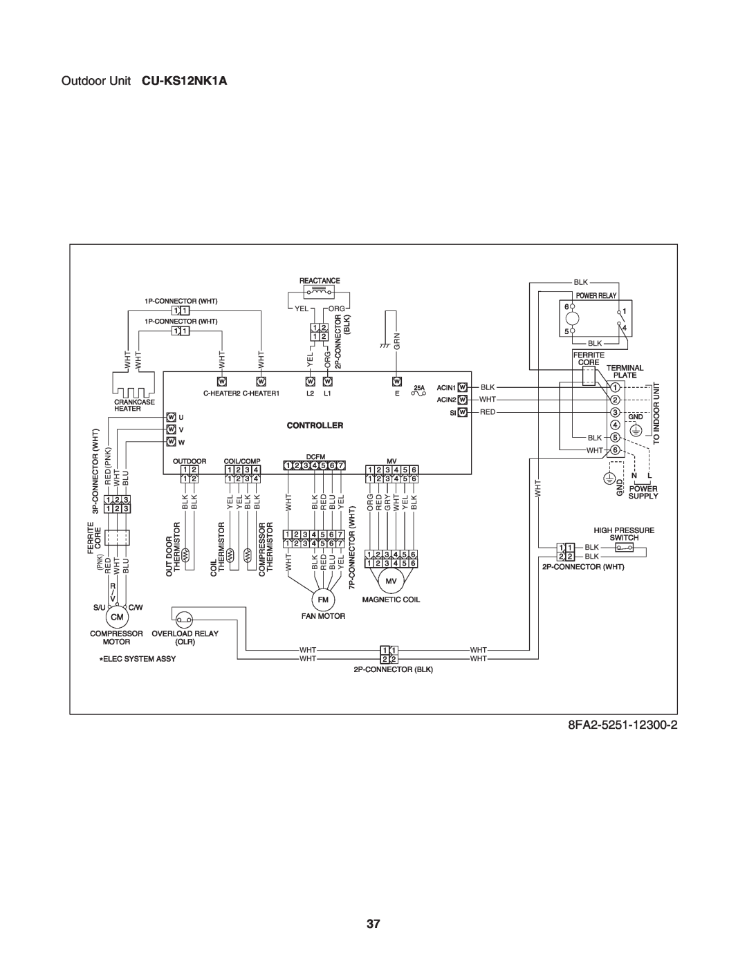
Outdoor Unit
CU-KS12NK1A
8FA2-5251-12300-2
37
Page 36
Page 38
Page 37
Image 37
Page 36
Page 38
Contents
CS-KS18NB4UWBody & CZ-18BT1UPanel
CS-KS12NB41Body & CZ-18BT1UPanel
CU-KS12NK1A
CU-KS18NKU CU-KS18NKUA
SAFETY PRECAUTIONS
which may cause a unit breakdown
Table of Contents
10. CHECKING ELECTRICAL COMPONENTS
Temperature
1. OPERATING RANGE
Temperature
Indoor Air Intake Temp
Unit Specifications
2. SPECIFICATIONS
2-1-1
Voltage Rating
Dimensions & Weight Outdoor Unit
Dimensions & Weight Indoor Unit
CS-KS18NB4UW& CZ-18BT1U
CU-KS18NKU
CS-KS18NB4UW& CZ-18BT1U
2-1-2. Indoor Unit
Outdoor Unit
CU-KS18NKU
Dimensions & Weight Outdoor Unit
Dimensions & Weight Indoor Unit
CS-KS18NB4UW& CZ-18BT1U
CU-KS18NKU
CS-KS12NB41& CZ-18BT1U
2-1-3. Indoor Unit
Outdoor Unit CU-KS12NK1A
Voltage Rating
Dimensions & Weight Outdoor Unit
Dimensions & Weight Indoor Unit
CS-KS12NB41& CZ-18BT1U
CS-KS18NB4UW& CZ-18BT1U
2-1-4. Indoor Unit
Outdoor Unit CU-KS18NKUA
230V
Dimensions & Weight Outdoor Unit
Dimensions & Weight Indoor Unit
CS-KS18NB4UW& CZ-18BT1U
Outdoor Unit CU-KS18NKUA
2-1-5. Indoor Unit
208V
Voltage Rating
Dimensions & Weight Outdoor Unit
Dimensions & Weight Indoor Unit
Indoor Unit
CS-KS18NB4UW& CZ-18BT1U
2-2-1.Indoor Unit
2-2.Major Component Specifications
Control PCB
Fan Motor
Fan Motor
Control PCB
Drain Pump
Heat Exchanger Coil
Control PCB
2-2-2.Outdoor Unit
Compressor
Fan Motor
Compressor
Control PCB
Fan Motor
Heat Exchanger Coil
Compressor
Control PCB
Fan Motor
Heat Exchanger Coil
Temperature F C
2-3.Other Component Specifications
Temperature F C
Temperature F C
3. DIMENSIONAL DATA
Unit inch mm
Unit inch mm
CU-KS18NKUA
4-1.Refrigerant Flow Diagram
4. REFRIGERANT FLOW DIAGRAM
Indoor unit
CU-KS18NKUA
Outdoor unit
5. PERFORMANCE DATA
5-1.Temperature Charts
Outdoor Unit CU-KS18NKUor CU-KS18NKUA
Indoor Unit CS-KS18NB4UW& CZ-18BT1U
CS-KS12NB41& CZ-18BT1U
5-2.Cooling Capacity
CU-KS12NK1A
Indoor Unit
Power Supply 230V Single Phase 60Hz
CS-KS18NB4UW& CZ-18BT1U
Outdoor Unit
CS-KS12NB41& CZ-18BT1U
5-3.Cooling Capacity Low Ambient
CU-KS12NK1A
CU-KS18NKUA
CS-KS18NB4UW& CZ-18BT1U
SHC Sensible Heat Capacity BTU/h
6. ELECTRICAL DATA
6-1.Electrical Characteristics
CU-KS18NKU
CS-KS18NB4UW& CZ-18BT1U
Cooling
Cooling
Indoor Unit
6-2.Electric Wiring Diagrams
CS-KS18NB4UW
CS-KS12NB41
8FA2-5251-12300-2
Outdoor Unit CU-KS12NK1A
Outdoor Unit CU-KS18NKU CU-KS18NKUA
7-1.Address Setting of the Remote Controller
7. MAINTENANCE
How to Connect
How to Disconnect
Pull the cover upward
7-3-1.Remove the air intake grill
7-3.Disassembly Procedure
7-3-3.Remove the ceiling panel
7-3-5.Remove the power box and control box
7-3-4.Remove the indoor air temperature sensor
CN07
Screw Ground cable
Screw Screw Screw
Screw
7-3-6.Remove the main body lower section
7-3-7.Remove the heat exchanger sensor
7-3-8.Remove the drain pump and float switch
7-3-10.Remove the heat exchanger
7-3-9.Remove the turbo fan and fan motor
8-1.Operation Functions
8. FUNCTIONS
Emergency operation
SENSOR DRY
Timer backup
HIGH POWER
NIGHT SETBACK
Lamp colors
8-2.Protective Functions
Compressor discharge temperature control
Freeze prevention
CT Peak current cut-offcontrol
9-2.Method of Self-Diagnostics
9. TROUBLESHOOTING BEFORE CALLING FOR SERVICE
PROCEDURE
HIGH POWER lamp
TIMER lamp
REMOTE CONTROL receiver
DIAGNOSIS CONTENTS
9-3.Checking the Indoor and Outdoor Units
3-1Condition E01
Before the Operation
Continued from the previous page A
3-2Condition E12
9-4-1.Indoor Fan Motor
9-4.Trouble Diagnosis of Fan Motor
Diagnostic procedure
9-4-2.Outdoor Fan Motor
Diagnostic results
Remedy for symptom 3 to
Trouble
Locations most susceptible to noise
Correction
Locations most susceptible to noise
10. CHECKING ELECTRICAL COMPONENTS
10-1-1.Power Supply Cord
10-1.Measurement of Insulation Resistance
10-1-2.Indoor Unit
10-2.Checking Continuity of Fuse on PCB Assy
11-1.Characteristics of New Refrigerant R410A
SPECIAL PRECAUTIONS WHEN SERVICING UNIT
11-1-1.What is New Refrigerant R410A?
11-1-3.Characteristics
Tubing precautions
11-2.Checklist before Servicing
Size of flare
No addition of compressor oil for R410A
11-3.Tools Specifically for R410A
11-4.Tubing Installation Procedures
11-5.In Case of Compressor Malfunction
11-5-1.Procedure for Replacing Compressor
Page
11-6.In Case Refrigerant is Leaking
11-7.Charging Additional Refrigerant
11-7-1.When Tubes are Extended
11-8. Retro-FittingExisting Systems
11-8-1.Use of Existing Units