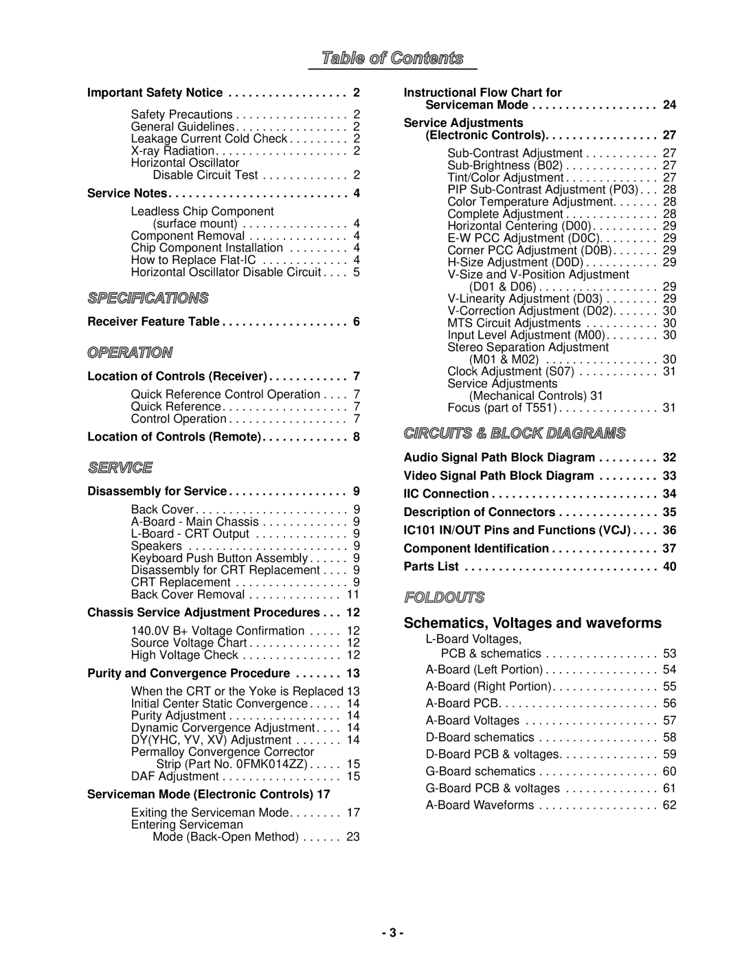
CT-32SX31E, CT-36SX31E, CT-32SX31CE, CT-32SX31UE, CT-36SX31CE specifications
The Panasonic CT-36SX31UE, CT-36SX31CE, CT-32SX31UE, CT-32SX31CE, and CT-36SX31E are part of Panasonic's renowned line of CRT (cathode-ray tube) televisions designed to deliver excellent picture quality and robust performance. These models are known for their advanced features, making them a popular choice for home entertainment enthusiasts.One of the key features of these televisions is their large screen sizes, with the CT-36SX31 models boasting a striking 36-inch display. The CT-32SX31 models, while slightly smaller at 32 inches, offer an equally immersive viewing experience. The screens are designed with high-resolution capabilities that enhance color depth and clarity, allowing viewers to enjoy a lifelike picture.
Panasonic has incorporated various technologies into these models, such as the Digital Comb Filter, which significantly reduces image distortion and enhances the overall picture quality. This feature allows for clearer images with improved color accuracy, making it ideal for watching movies and sports. Additionally, the models are equipped with a 3D Y/C separation processing feature that further elevates the quality of video playback by enhancing the precision of image separation.
Audio quality is also a focal point of these models. The television sets come with built-in speakers, providing powerful sound output that complements the stunning visuals. With features like surround sound capability, viewers can enjoy an enriched audio experience that brings movies and shows to life.
Connectivity is another essential aspect of these televisions. They are equipped with multiple input options, including composite, S-Video, and component inputs. This variety allows users to connect various devices like DVD players, gaming consoles, and cable boxes, facilitating a versatile entertainment setup.
Durability and reliability are characteristic of Panasonic products, and these models are no exception. Built with quality materials, they are designed to last, ensuring that consumers receive value for their investment.
In summary, the Panasonic CT-36SX31UE, CT-36SX31CE, CT-32SX31UE, CT-32SX31CE, and CT-36SX31E are standout CRT televisions renowned for their large screens, high-resolution image quality, excellent sound output, and robust connectivity options. While CRT technology has since transitioned to flat-panel displays, these models remain a testament to Panasonic's commitment to quality and performance in home entertainment.

