Getting Started
Installation
Connection Instructions
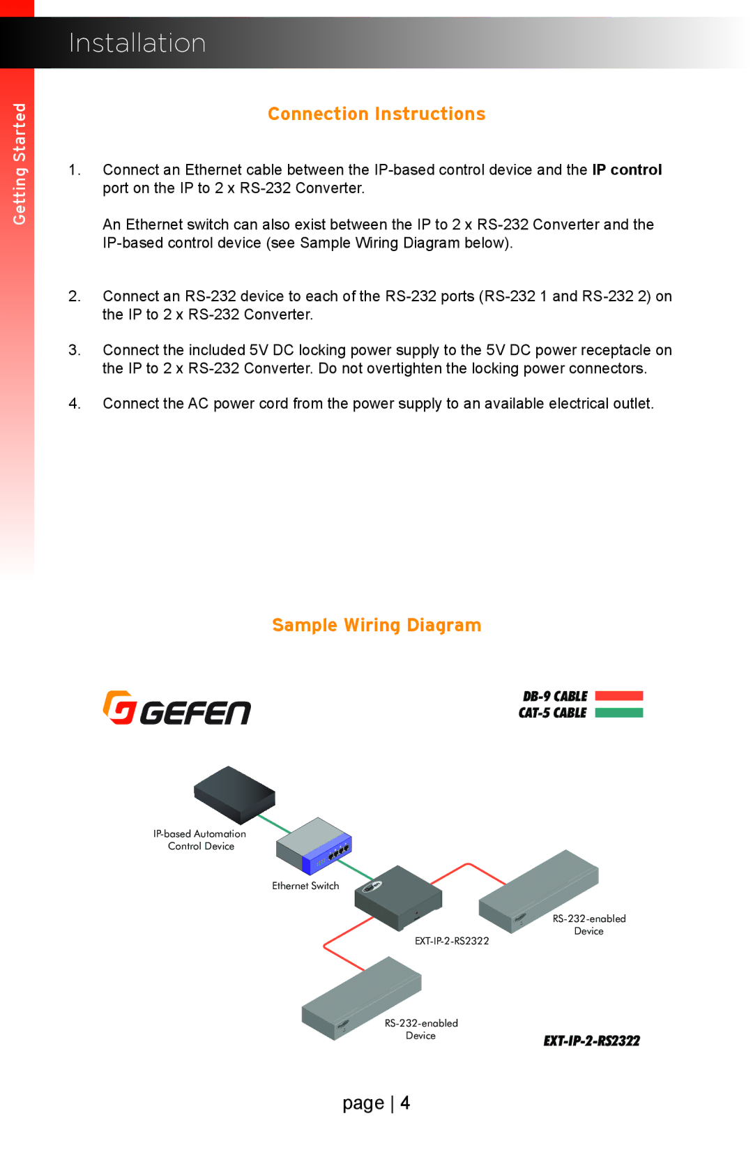
1.Connect an Ethernet cable between the
An Ethernet switch can also exist between the IP to 2 x
2.Connect an
3.Connect the included 5V DC locking power supply to the 5V DC power receptacle on the IP to 2 x
4.Connect the AC power cord from the power supply to an available electrical outlet.
Sample Wiring Diagram
DB-9 CABLE
CAT-5 CABLE
Control Device
Ethernet Switch
Device
Device
page 4
