Manuals
/
Panasonic
/
Household Appliance
/
Air Conditioner
Panasonic
CU-2S18NBU-1
service manual
Electronic Circuit Diagram
Models:
CU-2S18NBU-1
1
11
43
43
Download
43 pages
32.39 Kb
8
9
10
11
12
13
14
15
Troubleshooting
Specifications
Operation Characteristics
Install
Refrigeration Cycle Diagram
Wiring Error Check
Dimension
Outdoor Unit Removal Procedure
Safety Precautions
Powerful Operation
Page 11
Image 11
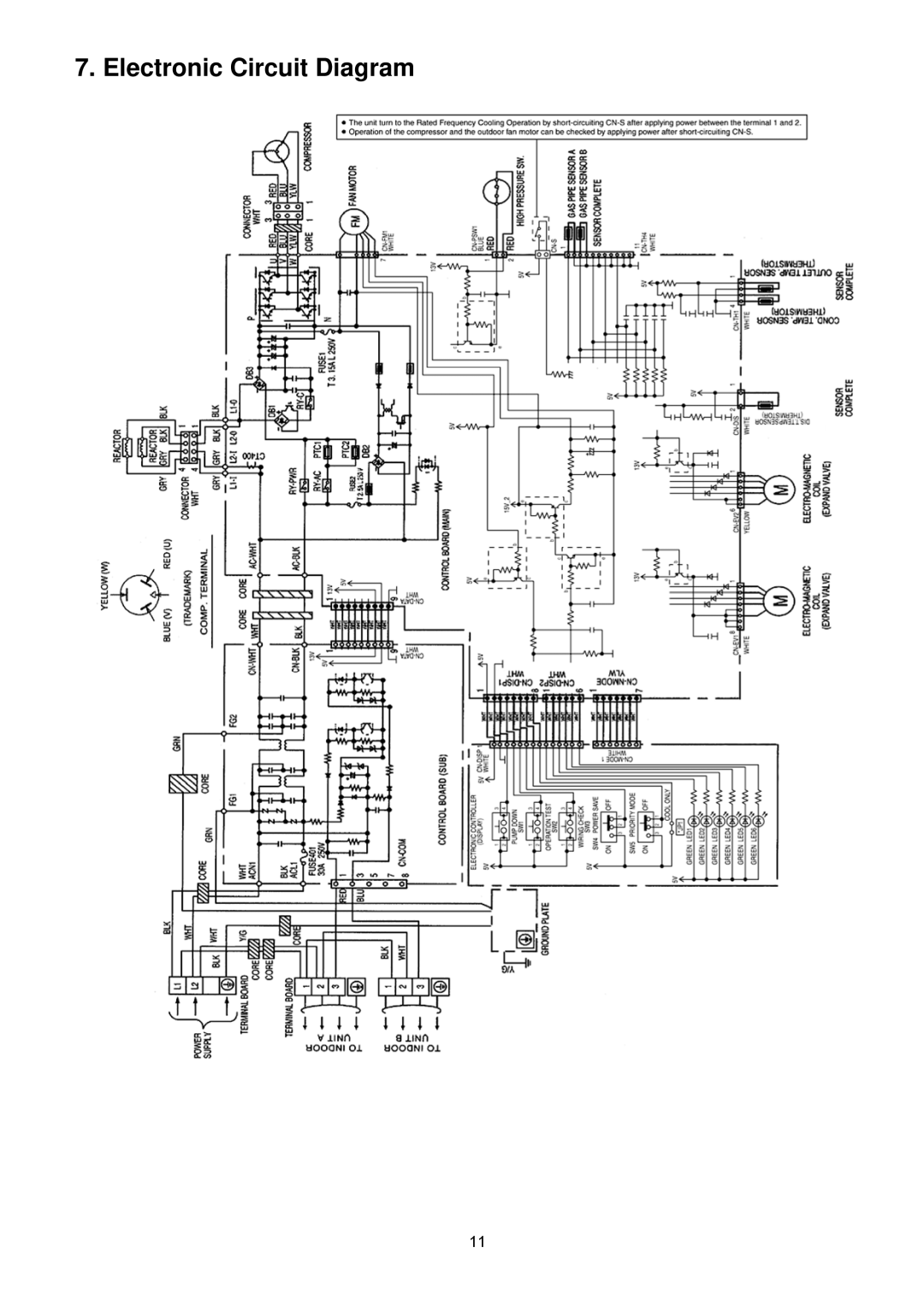
7. Electronic Circuit Diagram
11
Page 10
Page 12
Page 11
Image 11
Page 10
Page 12
Contents
Table of Contents
Disassembly and Assembly Instructions
Items to be followed are classified by the symbols
Safety Precautions
Page
Model Outdoor Unit CU-2S18NBU-1
Specification
Multi split combination possibility
Dimensions
Refrigeration Cycle Diagram
Block Diagram
Wiring Connection Diagram
Electronic Circuit Diagram
Main Printed Circuit Board
Printed Circuit Board
Noise Filter Printed Circuit Board
Check Points
Installation Information
Outdoor Unit Installation Diagram
Installation Instruction
Outdoor Unit Installation Guidelines
Gas Leak Checking
Connecting the Piping to Outdoor Unit
Evacuation of the Equipment
Heat Insulation
Outdoor fan control
Powerful Operation
Operation Control
Cooling Operation
Freeze Prevention control Cool
Electronic Parts Temperature Rise Protection 1 Cool
Electronic Parts Temperature Rise Protection 2 Cool
Protection Control
12.7 30 seconds Force Operation
Time Delay Safety Control Restart Control
IPM power transistor Protection Control
Cooling overload control Cool
Compressor discharge high pressure protection control
Compressor Protection Control Gas leak detection control
Valve close detection control
Test Operation
Servicing Mode
Wiring Error Check
Pump Down Operation
Mode priority function
Power Save Mode
Self Diagnosis Function
Troubleshooting Guide
Indoor high Check indoor heat Exchanger
Remove the Control Board Cover and Particular Plates
Disassembly and Assembly Instructions
Outdoor Unit Removal Procedure
Removing the Cabinet Top Plate and Cabinet Front Plate
Removing the Propeller Fan and Fan Motor
Removing the Control P.C. Board
Page
CS-S9NKUW-1 CU-2S18NBU-1
Technical Data
Operation Characteristics
Page
CS-S9NKUW-1x2 CU-2S18NBU-1
Page
CS-S12NKUW-1 CU-2S18NBU-1
Page
CS-S12NKUW-1x2 CU-2S18NBU-1
Page
CS-S12NKUW-1+CS-S9NKUW-1 CU-2S18NBU-1
Page
Exploded View and Replacement Parts List
REF. no Description & Name QTY
Shock Absorber Left
Top
Page
Image
Contents