10.4 EVACUATION OF THE EQUIPMENT
WHEN INSTALLING AN AIR CONDITIONER, BE
SURE TO EVACUATE THE AIR INSIDE THE
INDOOR UNIT AND PIPES in the following procedure.
1.Connect a charging hose with a push pin to the Low side of a charging set and the service port of the gas side
2.Connect the micron gauge between vacuum pump and service port of outdoor units.
3.Turn on the power switch of the vacuum pump and make sure that connect digital micron gauge and to pull down to a value of 500 microns.
4.To make sure micron gauge a value 500 microns and close the low side valve of the charging set and turn off the vacuum pump.
5.Disconnect the vacuum pump house from the service port of the
6.Tighten the service port caps of gas side
7.Remove the valve caps of both of the
8.Mount valve caps onto the
•Be sure to check for gas leakage.
![]() CAUTION
CAUTION
•If micron gauge value does not descend 500 microns, take the following measures:
oIf the leak stops when the piping connections are tightened further, continue working from step e. o If the leak does not stop when the connections are retightened, repair location of leak.
o Do not release refrigerant during piping work for installation and reinstallation. o Take care when handling the liquid refrigerant, it may cause frostbite.
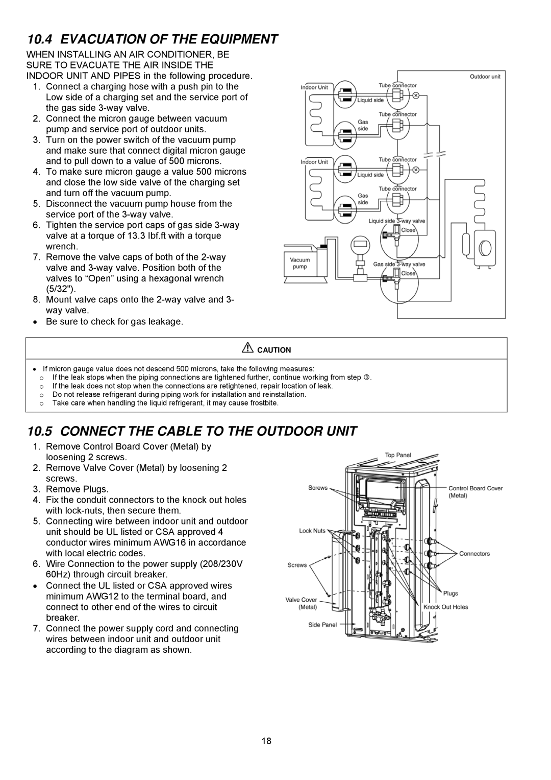
10.5 CONNECT THE CABLE TO THE OUTDOOR UNIT
1.Remove Control Board Cover (Metal) by loosening 2 screws.
2.Remove Valve Cover (Metal) by loosening 2 screws.
3.Remove Plugs.
4.Fix the conduit connectors to the knock out holes with
5.Connecting wire between indoor unit and outdoor unit should be UL listed or CSA approved 4 conductor wires minimum AWG16 in accordance with local electric codes.
6.Wire Connection to the power supply (208/230V 60Hz) through circuit breaker.
•Connect the UL listed or CSA approved wires minimum AWG12 to the terminal board, and connect to other end of the wires to circuit
breaker.
7.Connect the power supply cord and connecting wires between indoor unit and outdoor unit according to the diagram as shown.
18