How to wire the remote controller

Fig. 8-a How to wire the remote controller

(1)

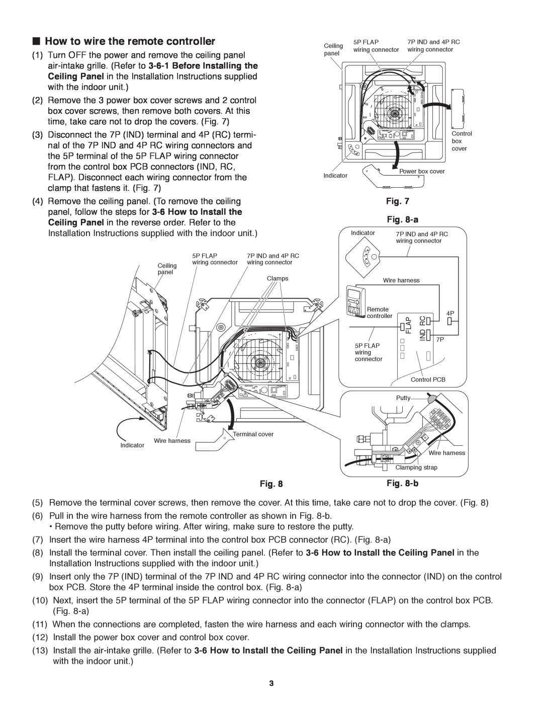
Turn OFF the power and remove the ceiling panel


air-intake grille. (Refer to 3-6-1 Before Installing the


Ceiling Panel in the Installation Instructions supplied


with the indoor unit.)

(2)

Remove the 3 power box cover screws and 2 control


box cover screws, then remove both covers. At this


time, take care not to drop the covers. (Fig. 7)

Ceiling


5P FLAP


7P IND and 4P RC


wiring connector


wiring connector

panel


(3) Disconnect the 7P (IND) terminal and 4P (RC) termi-

nal of the 7P IND and 4P RC wiring connectors and

the 5P terminal of the 5P FLAP wiring connector

from the control box PCB connectors (IND, RC,

FLAP). Disconnect each wiring connector from the

clamp that fastens it. (Fig. 7)

Indicator

Control box cover

Power box cover

(4) Remove the ceiling panel. (To remove the ceiling

panel, follow the steps for 3-6 How to Install the

Ceiling Panel in the reverse order. Refer to the

Installation Instructions supplied with the indoor unit.)


5P FLAP


7P IND and 4P RC


Ceiling


wiring connector


wiring connector


panel


Clamps


Fig. 7


Fig. 8-a


Indicator


7P IND and 4P RC


wiring connector


Wire harness


Remote


4P

controller


FLAP

IND RC


5P FLAP


7P

wiring


connector


Control PCB


Putty


Terminal cover

Wire harness

Indicator

Fig. 8-bManual backgroundManual backgroundManual backgroundManual backgroundManual backgroundManual background Wire harness

Clamping strap

Fig. 8

Fig. 8-b

(5)Remove the terminal cover screws, then remove the cover. At this time, take care not to drop the cover. (Fig. 8)

(6)Pull in the wire harness from the remote controller as shown in Fig. 8-b.

‡Remove the putty before wiring. After wiring, make sure to restore the putty.

(7)Insert the wire harness 4P terminal into the control box PCB connector (RC). (Fig. 8-a)

(8)Install the terminal cover. Then install the ceiling panel. (Refer to 3-6 How to Install the Ceiling Panel in the Installation Instructions supplied with the indoor unit.)

(9)Insert only the 7P (IND) terminal of the 7P IND and 4P RC wiring connector into the connector (IND) on the control box PCB. Store the 4P terminal inside the control box. (Fig. 8-a)

(10)Next, insert the 5P terminal of the 5P FLAP wiring connector into the connector (FLAP) on the control box PCB. (Fig. 8-a)

(11)When the connections are completed, fasten the wire harness and each wiring connector with the clamps.

(12)Install the power box cover and control box cover.

(13)Install the air-intake grille. (Refer to 3-6 How to Install the Ceiling Panel in the Installation Instructions supplied with the indoor unit.)

3

Page 27
Image 27
Panasonic CZ-RD515U service manual How to wire the remote controller, Fig, b

CZ-RD515U specifications

Panasonic has consistently been a leader in providing effective HVAC solutions, and the CZ-RD515U model exemplifies this dedication. This advanced remote controller is designed to enhance the user experience when managing Panasonic’s air conditioning and heat pump systems.

One of the standout features of the CZ-RD515U is its versatility. The remote can control multiple indoor units, making it suitable for both residential and commercial applications. The device supports a variety of operation modes, including cooling, heating, and auto mode, allowing users to tailor the climate control to their specific needs.

The unit boasts a clear LCD display that shows operational status, temperature settings, and mode selection, ensuring easy readability from a distance. Users can effortlessly adjust temperature settings to maintain an optimal comfort level using intuitive buttons. Additionally, the remote features a timer function, allowing users to program start and stop times for their HVAC systems, which helps in saving energy and improving efficiency.

Another significant technology integrated into the CZ-RD515U is the super quiet operation mode. This feature allows users to set their air conditioning system to operate at lower noise levels, making it ideal for nighttime use or quiet zones. Furthermore, the remote controller includes a "powerful" function, which provides a temporary boost in power to reach desired temperatures more quickly, enhancing overall comfort in the space.

Panasonic has also incorporated a user-friendly design into the CZ-RD515U, with a lightweight structure and ergonomic grip, making it easy to hold and operate. The remote is equipped with a protective cover to safeguard against dust while not in use. Each remote can function under a considerable distance range, providing convenience in larger spaces.

Moreover, the CZ-RD515U takes advantage of advanced wireless communication, ensuring reliable control without the hindrances of wired connections. This flexibility underlines Panasonic’s commitment to user-centric design, merging functionality with cutting-edge technology to deliver superior comfort solutions.

Ultimately, the Panasonic CZ-RD515U stands out for its thoughtful features and functionalities, making it a reliable and efficient option for controlling your heating and cooling systems effortlessly. Its advanced capabilities, ease of use, and quiet operation make it a valuable addition to any home or business environment.