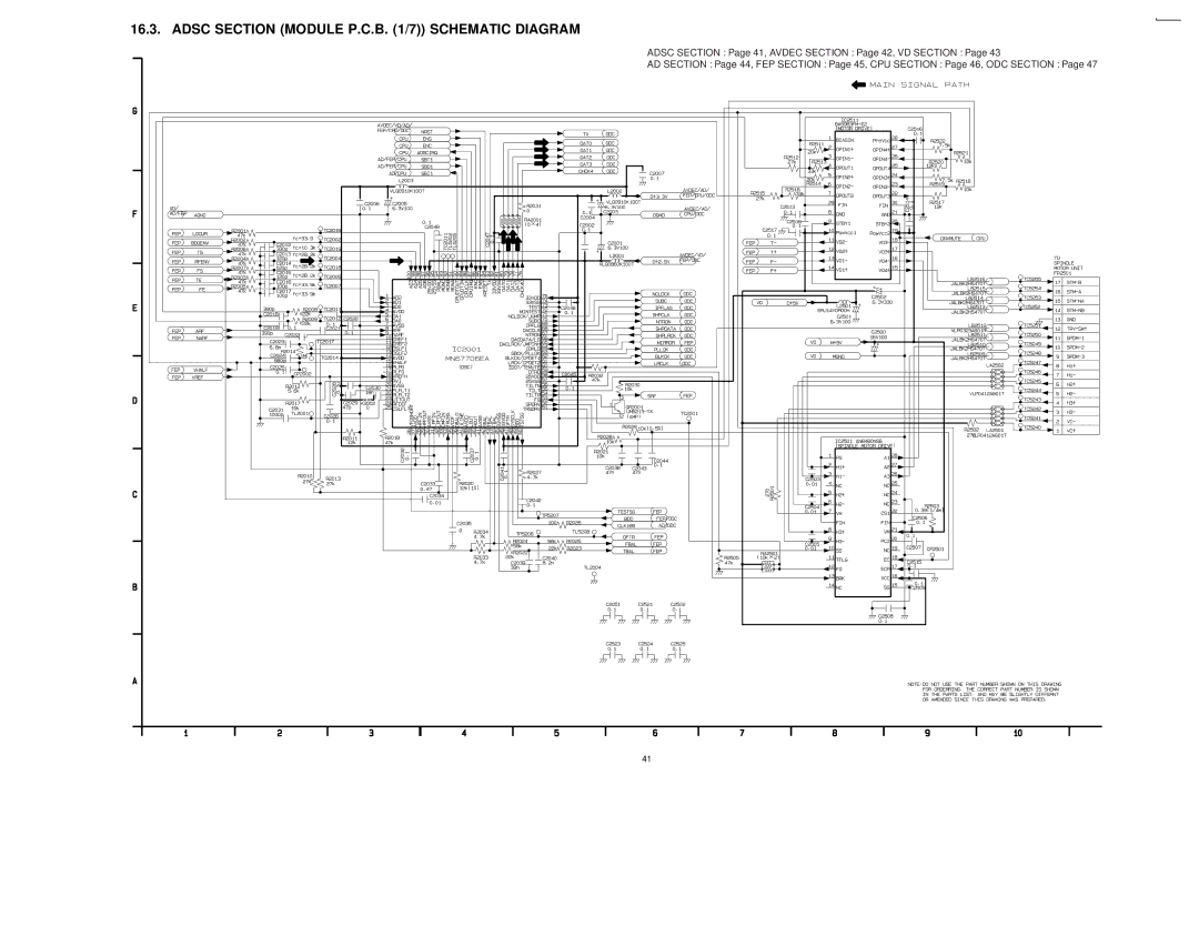
DVD Player
Specifications
DVD-RV60
Area
Page
CONTENTS
Page
18 EXPLODED VIEWS
17 PRINTED CIRCUIT BOARD DIAGRAM
19 REPLACEMENT PARTS LIST
1.1. GENERAL GUIDELINES
1 SAFETY PRECAUTIONS
1.1.1. LEAKAGE CURRENT COLD
1.1.2. LEAKAGE CURRENT HOT CHECK
4 HANDLING PRECAUTIONS FOR TRAVERSE DECK
3 PRECAUTION OF LASER DIODE
4.1. Handling of optical pickup
4.2. Grounding for electrostatic breakdown prevention
5 Optical Pickup Self-Diagnosis and Replacement Procedure
6.2. Self-Diagnosis Function UHF Display
6 Self-Diagnosis Function and Service Modes
6.1. Service Mode Table
6.4.1. Setting Method
6.3. Examples of Repairs Using Error Codes
6.4. Sales Demonstration Lock Function
6.4.2. Release Method
7.2. Storing and Handling Test Discs
7 Service Tools and Equipment
7.1. Service Tools and Equipment Table
8 General Description
Remote control
8.1. Operating Instructions
Main unit
DVD-RV60
9.1. Disassembly Procedure
9 Assembling and Disassembling the Casing and Checking P.C.B.s
DVD-RV60
9.2. Casing Parts and P.C.B. Positions 9.3. Service Positions
9.6. Disassembling the Front Panel
9.4. Disassembling the Top Cover
9.5. Disassembling the Tray
9.9. Disassembling the Rear Panel
9.7. Disassembling the Loading Base Unit
9.8. Checking the Module P.C.B
9.11. Checking the Mother P.C.B
9.10. Checking the Power Supply P.C.B
9.13. Checking the Power Switch P.C.B
9.12. Checking the Front Switch P.C.B
1. Remove the 3 screws
1. Remove the 2 screws
10.1.1. Precautions
10 Service Precautions
10.2.2. Precautions
10.1. Initializing the DVD Player
11.1. Handling the Optical Pickup
11.2. Disassembly Procedure
11 Assembling and Disassembling the Optical Pickup Mechanical Parts
DVD-RV60
11.3. Disassembling the Clamp Base Unit
11.5. Disassembling the Traverse Unit
11.6. Disassembling the Stepping Motor Unit
11.7. Disassembling the Optical Pickup Unit
11.10. Assembling the Optical Pickup
11.8. Disassembling the Nut Unit
11.9. Disassembling the Sub-Shaft Preload Spring
3. Remove the solder from the pickup FPC´s soldered short- circuit
11.11. Disassembling the Spindle Motor Unit
1. Remove the three screws
DVD-RV60
DVD-RV60
11.12. Optical Pickup Tilt Adjustment
· Optical adjutments cannnot be made inside the optical pickup
11.16. Disassembling the Mechanism Loading P.C.B
11.15. Disassembling the Pulley Gear and Deceleration Gear
11.13. Disassembling the Intermediate Chassis
11.14. Disassembling the Vertical cam and Drive gear
12.2. Video Output Chrominance Signal Adjustment
12 Electrical Adjustment
12.1. Video Output Luminance Signal Adjustment
12.3. Video Component Signal CB Output Adjustment
13 Abbreviations
INITIAL/LOGO
14.1. POWER SUPPLY P.C.B
14 VOLTAGE CHART
14.2
MODULE P.C.B
DVD-RV60
DVD-RV60
DVD-RV60
MOTHER P.C.B
14.3
DVD-RV60
15.1. OVERALL BLOCK DIAGRAM
15 BLOCK DIAGRAM
MECHANISM UNIT
MOTHER P.C.B
15.2. SERVO BLOCK DIAGRAM
XRESET
15.3. VIDEO BLOCK DIAGRAM
VIDEO OUT
SCLOCK
STBDAC
15.4. AUDIO BLOCK DIAGRAM
16.1. INTERCONNECTION SCHEMATIC DIAGRAM
16 SCHEMATIC DIAGRAM
16.2. POWER SUPPLY SCHEMATIC DIAGRAM
ADSC SECTION Page 41, AVDEC SECTION Page 42, VD SECTION Page
16.3. ADSC SECTION MODULE P.C.B. 1/7 SCHEMATIC DIAGRAM
ADSC SECTION Page 41, AVDEC SECTION Page 42, VD SECTION Page
16.4. AV DECORDER SECTION MODULE P.C.B. 2/7 SCHEMATIC DIAGRAM
ADSC SECTION Page 41, AVDEC SECTION Page 42, VD SECTION Page
16.5. VIDEO D/A CONVERTER SECTION MODULE P.C.B. 3/7 SCHEMATIC DIAGRAM
ADSC SECTION Page 41, AVDEC SECTION Page 42, VD SECTION Page
16.6. AUDIO SECTION MODULE P.C.B. 4/7 SCHEMATIC DIAGRAM
ADSC SECTION Page 41, AVDEC SECTION Page 42, VD SECTION Page
16.7. FEP SECTION MODULE P.C.B. 5/7 SCHEMATIC DIAGRAM
ADSC SECTION Page 41, AVDEC SECTION Page 42, VD SECTION Page
16.8. CPU SECTION MODULE P.C.B. 6/7 SCHEMATIC DIAGRAM
ADSC SECTION Page 41, AVDEC SECTION Page 42, VD SECTION Page
16.9. ODC SECTION MODULE P.C.B. 7/7 SCHEMATIC DIAGRAM
VO SECTION Page 48, AO SECTION Page 49, OP SECTION Page
16.10. VIDEO OUT SECTION MOTHER P.C.B. 1/3 SCHEMATIC DIAGRAM
VO SECTION Page 48, AO SECTION Page 49, OP SECTION Page
16.11. AUDIO OUT SECTION MOTHER P.C.B. 2/3 SCHEMATIC DIAGRAM
VO SECTION Page 48, AO SECTION Page 49, OP SECTION Page
16.12. OPERATION SECTION MOTHER P.C.B. 3/3 SCHEMATIC DIAGRAM
16.13. FRONT SWITCH AND POWER SWITCH SCHEMATIC DIAGRAM
Page
17.1. POWER SUPPLY P.C.B
17 PRINTED CIRCUIT BOARD DIAGRAM
POWER SUPPLY P.C.B
IC1101
CONPONENT SIDE
17.2. MODULE P.C.B. 1/2 COMPONENT SIDE
MODULE P.C.B. 1/2
MODULE P.C.B. 2/2
17.3. MODULE P.C.B. 2/2 FOIL SIDE
FOIL SIDE
D C B A
17.4. MODULE P.C.B. AND MOTHER P.C.B. ADDRESS INFORMATION
MOTHER P.C.B
17.5. MOTHER P.C.B
MECHANISM
LOADING
FRONT SWITCH P.C.B
17.6. FRONT SWITCH P.C.B. AND POWER SWITCH P.C.B
POWER SWITCH
P.C.B
DVD-RV60
18 EXPLODED VIEWS
18.1. Casing Parts & Mechanism Section Exploded View
DVD-RV60
18.2. Loading Mechanism Section Exploded View
When replacing parts, lubricate the parts marked “×××” in the diagram
18.3. Traverse Section Exploded View
DVD-RV60
18.4. Packing & Accessories Section Exploded View
Section Parts List
19 REPLACEMENT PARTS LIST
Parts List
19.1. Casing Parts & Mechanism
Section Parts List
19.3. Traverse Section Parts List
19.4. Packing & Accessories
19.5. Electrical Replacement Parts List
Ref. No
Ref. No
Ref. No
Ref. No
Ref. No
Ref. No
Ref. No
Ref. No
Ref. No
Ref. No
Ref. No
H000500000TK/TT