EX-10
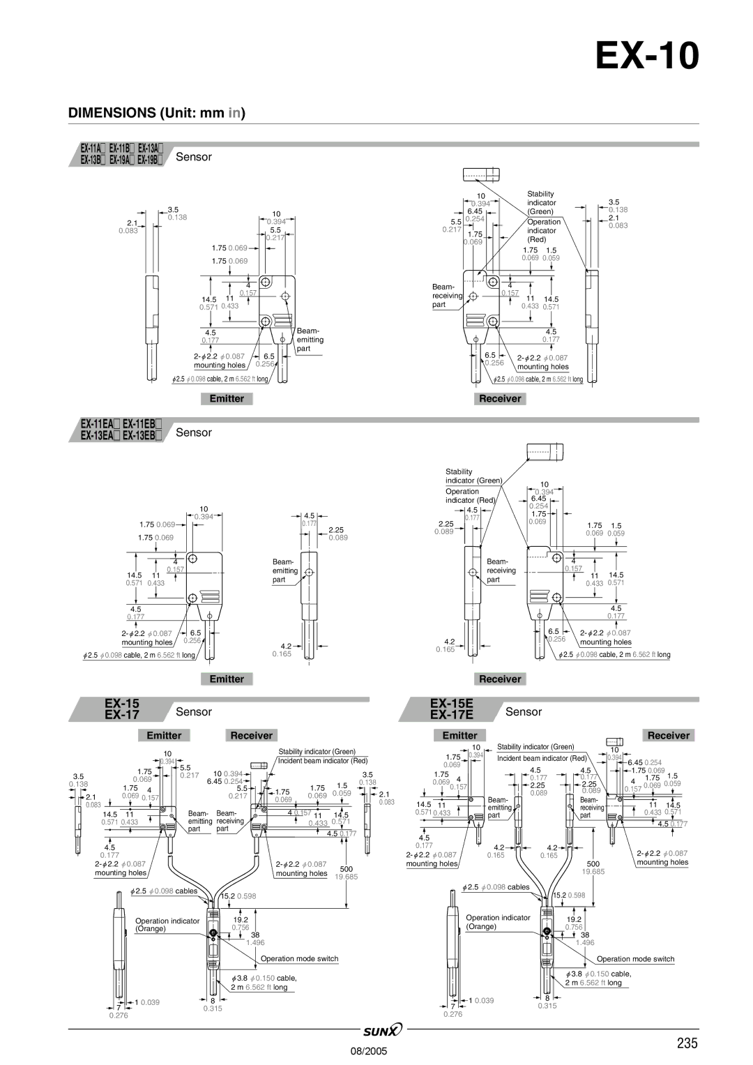
DIMENSIONS (Unit: mm in)
2.1
0.083
Sensor |
|
|
3.5 |
| 10 |
0.138 |
| |
| 0.394 | |
|
| |
|
| 5.5 |
|
| 0.217 |
1.75 0.069 |
| |
1.75 0.069 |
| |
| 4 |
|
14.5 | 0.157 | |
11 |
| |
0.571 0.433 |
| |
4.5 |
| Beam- |
0.177 |
| emitting |
part | ||
6.5 | ||
mounting holes | 0.256 | |
"2.5 "0.098 cable, 2 m 6.562 ft long | ||
| 10 | Stability | 3.5 |
| 0.394 | indicator | |
| 6.45 | (Green) | 0.138 |
5.5 | 0.254 | Operation | 2.1 |
0.217 |
| indicator | 0.083 |
1.75 |
| ||
| 0.069 | (Red) |
|
|
|
|
1.751.5
0.069 0.059
Beam- |
|
| 4 |
|
receiving |
| 0.157 |
| |
|
| 11 | 14.5 | |
part |
|
| ||
|
| 0.433 | 0.571 | |
|
|
|
| 4.5 |
|
|
|
| 0.177 |
| 6.5 |
| "0.087 | |
| 0.256 | |||
| mounting holes | |||
|
|
| ||
"2.5 "0.098 cable, 2 m 6.562 ft long
Emitter
Sensor | |
Receiver
10
![]() 0.394
0.394
1.750.069
1.750.069
4
0.157
14.5 11
0.571 0.433
4.5 |
|
0.177 |
|
6.5 | |
mounting holes | 0.256 |
"2.5 "0.098 cable, 2 m 6.562 ft long
![]() 4.5
4.5 ![]()
0.177
2.25
0.089
Beam- emitting part
4.2
0.165
Stability |
|
|
| |
indicator (Green) | 10 |
|
| |
Operation |
|
| ||
0.394 |
|
| ||
indicator (Red) | 6.45 |
|
| |
4.5 | 0.254 |
|
| |
1.75 |
|
| ||
0.177 |
|
| ||
0.069 |
|
| ||
2.25 | 1.75 | 1.5 | ||
| ||||
0.089 |
| 0.069 | 0.059 | |
Beam- |
| 4 |
| |
receiving |
| 0.157 | 14.5 | |
part |
| 11 | ||
| 0.433 | 0.571 | ||
|
|
|
| 4.5 |
|
| 0.177 |
| 6.5 | |
4.2 | 0.256 | mounting holes |
0.165 | "2.5 | "0.098 cable, 2 m 6.562 ft long |
|
EmitterReceiver
| Sensor |
| Sensor |
|
|
Emitter | Receiver | Emitter |
Receiver |
10 ![]() 0.394
0.394
3.5 | 1.75 | ||
0.069 | |||
0.138 | |||
1.75 | 4 | ||
| |||
2.1 | 0.069 | ||
0.157 | |||
0.083 |
|
| |
14.5 | 11 |
| |
0.571 0.433 |
| ||
4.5
0.177
5.5 | 10 0.394 |
0.217 |
6.450.254![]()
5.5![]()
0.217
Beam- Beam- emitting receiving
part part
Stability indicator (Green) |
|
|
|
|
| 10 | ||
|
|
| 1.75 | 0.394 | ||||
Incident beam indicator (Red) |
|
| ||||||
|
| 0.069 |
| |||||
|
|
|
|
|
|
| ||
|
|
| 3.5 |
|
| 1.75 | 4 |
|
|
| 1.5 | 0.138 |
|
| 0.069 |
| |
1.75 | 1.75 |
|
| 0.157 |
| |||
0.069 | 0.059 |
| 2.1 |
|
|
|
| |
0.069 |
|
|
| 0.083 | 14.5 | 11 |
|
|
|
|
|
|
|
| |||
|
|
|
|
|
|
| ||
4 0.157 11 | 14.5 |
|
| 0.571 0.433 |
| |||
| 0.433 | 0.571 |
|
|
|
|
|
|
| 4.5 0.177 |
|
| 4.5 |
|
|
| |
|
|
|
|
|
|
|
| |
|
|
|
|
| 0.177 |
|
|
|
|
|
|
|
|
| |||
500 |
|
| mounting holes |
| ||||
|
|
|
|
|
|
|
| |
mounting holes 19.685
Stability indicator (Green) | 10 |
|
Incident beam indicator (Red) | 0.394 6.45 0.254 |
| ||||
| 4.5 | 4.5 | 1.75 0.069 | 1.5 | ||
| 0.177 | 0.177 | 4 |
| 1.75 | |
| 2.25 | 2.25 |
| 0.069 0.059 | ||
| 0.089 | 0.089 | 0.157 |
|
| |
Beam- | Beam- |
|
|
|
| |
|
|
| 11 | 14.5 | ||
emitting |
| receiving |
|
| ||
part |
| part |
|
| 0.433 0.571 | |
|
|
|
|
| ||
|
|
|
|
| 4.5 0.177 | |
4.2 | 4.2 |
|
| |||
0.165 | 0.165 |
|
| |||
|
| 500 |
| mounting holes | ||
|
| 19.685 |
|
|
|
|
"2.5 "0.098 cables | 15.2 0.598 |
| |
Operation indicator | 19.2 |
(Orange) | 0.756 |
38
1.496
Operation mode switch
"3.8 "0.150 cable, 2 m 6.562 ft long
1 0.039 | 8 |
7 | 0.315 |
0.276
"2.5 "0.098 cables
15.2 0.598
Operation indicator | 19.2 |
(Orange) | 0.756 |
![]() 38 1.496
38 1.496
Operation mode switch
"3.8 "0.150 cable, 2 m 6.562 ft long
| 1 0.039 | 8 | |
7 | 0.315 | ||
|
0.276
08/2005 | 235 |
|