4 ASSEMBLY INSTRUCTIONS
CAUTION:
The proper operation of the “off lock lever” is critical for the safe use and operation of the saw/cutter. Be extra careful in re- assembling the unit and ensure that the “off lock lever” is properly positioned. Verify the operation of the “off lock lever” upon completing the
■MAIN UNIT ASSEMBLY.
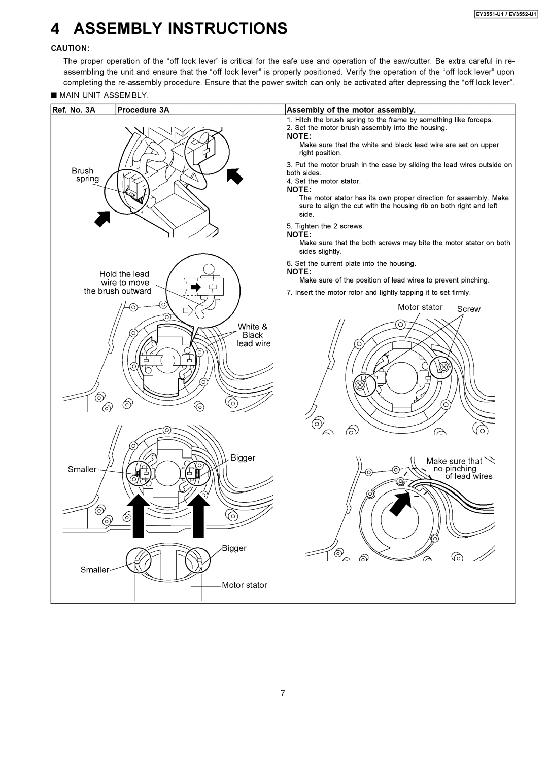
Ref. No. 3A | Procedure 3A | Assembly of the motor assembly. | |
|
| 1. | Hitch the brush spring to the frame by something like forceps. |
|
| 2. | Set the motor brush assembly into the housing. |
NOTE:
Make sure that the white and black lead wire are set on upper right position.
3.Put the motor brush in the case by sliding the lead wires outside on both sides.
4.Set the motor stator.
NOTE:
The motor stator has its own proper direction for assembly. Make sure to align the cut with the housing rib on both right and left side.
5.Tighten the 2 screws.
NOTE:
Make sure that the both screws may bite the motor stator on both sides slightly.
6.Set the current plate into the housing.
NOTE:
Make sure of the position of lead wires to prevent pinching. 7. Insert the motor rotor and lightly tapping it to set firmly.
7