V. ASSEMBLY
Attaching or Removing Bit
NOTE:
When attaching or removing a bit, disconnect battery pack from tool or place the switch in the center position (switch lock).
This tool is equipped with a keyless drill chuck.
1.Attachment
Insert the bit and turn the lock collar clockwise (looking from the front) to tighten firmly until it stops clicking.
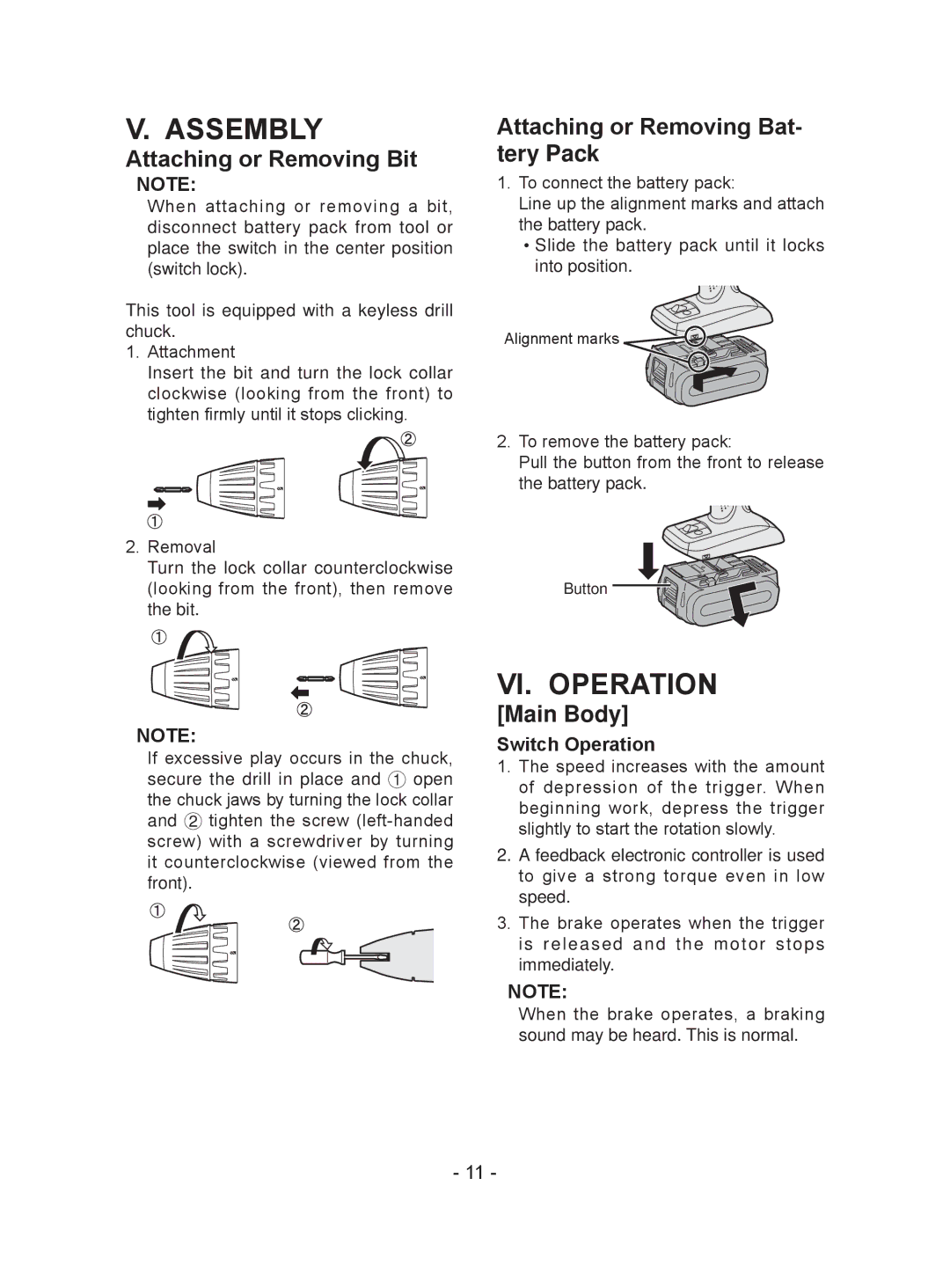
Attaching or Removing Bat- tery Pack
1.To connect the battery pack:
Line up the alignment marks and attach the battery pack.
●●Slide the battery pack until it locks into position.
Alignment marks![]()
![]()
![]()
![]()
![]()
![]()
2.To remove the battery pack:
Pull the button from the front to release the battery pack.
2. Removal
Turn the lock collar counterclockwise
(looking from the front), then removeButton the bit.
NOTE:
If excessive play occurs in the chuck, secure the drill in place and 1 open the chuck jaws by turning the lock collar and 2 tighten the screw
VI. OPERATION
[Main Body]
Switch Operation
1.The speed increases with the amount of depression of the trigger. When beginning work, depress the trigger slightly to start the rotation slowly.
2.A feedback electronic controller is used to give a strong torque even in low speed.
3.The brake operates when the trigger is released and the motor stops immediately.
NOTE:
When the brake operates, a braking sound may be heard. This is normal.
- 11 -