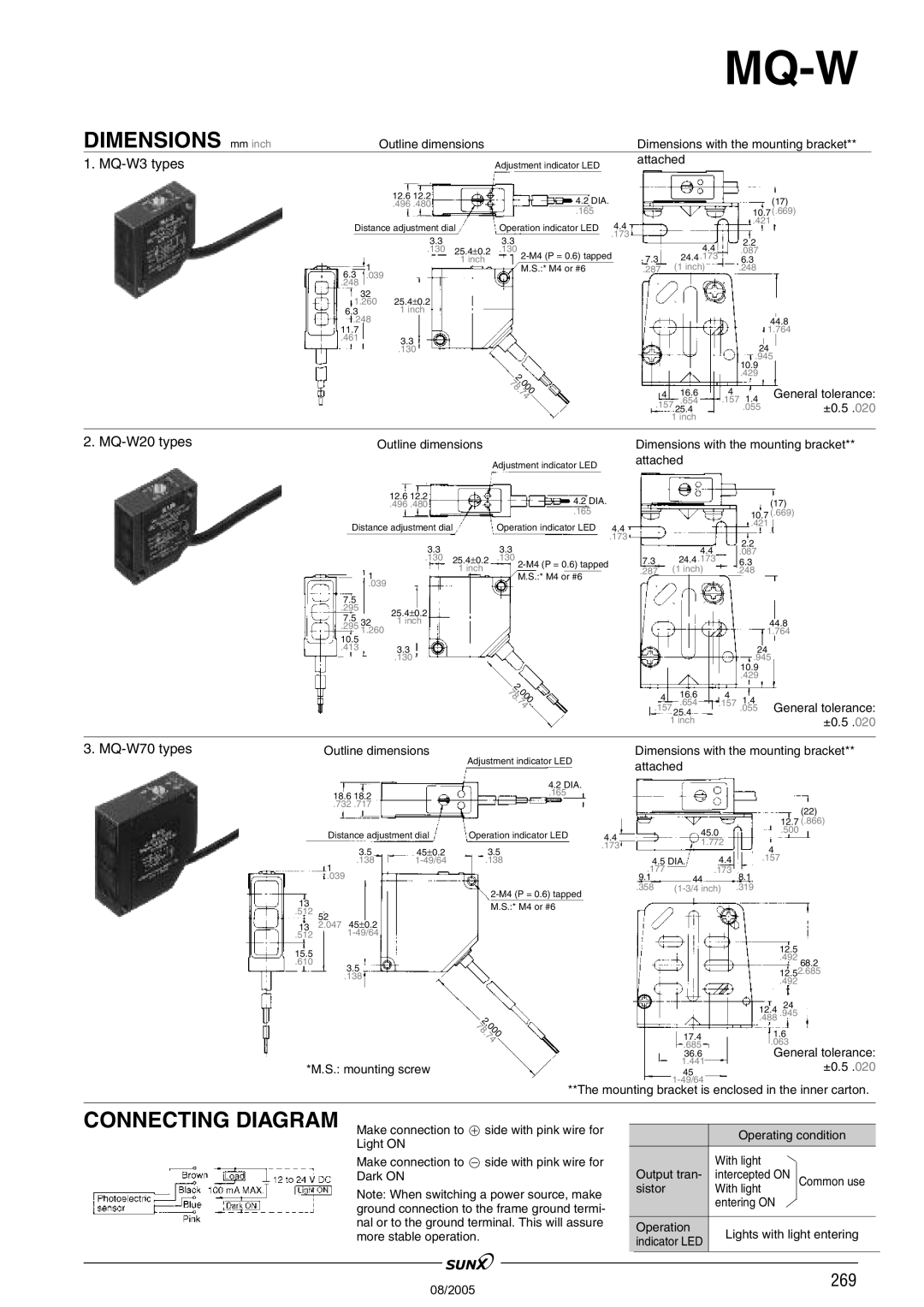
MQ-W3, MW-W20 specifications
Panasonic, a brand synonymous with innovation and quality in home appliances, introduces the MW-W20 and MQ-W3 rice cookers, each designed to enhance the culinary experience for rice enthusiasts. These models exemplify advanced technology, versatility, and user-friendly features, making them essential kitchen companions.The Panasonic MW-W20 is equipped with an intelligent Fuzzy Logic technology, which allows the cooker to automatically adjust cooking time and temperature based on the type of rice being prepared. This ensures perfect, fluffy rice with minimal effort. The MW-W20 has a capacity of up to 1 liter, making it ideal for small to medium-sized families. Its compact design does not compromise on performance, featuring a non-stick inner pot that simplifies both cooking and cleaning.
This model is also equipped with a variety of cooking settings, allowing users to prepare not only white and brown rice but also porridge and even steaming vegetables, showcasing its versatility. The keep-warm function ensures that meals stay at the optimal temperature until ready to serve. A user-friendly LED display and intuitive buttons enable seamless operation.
On the other hand, the Panasonic MQ-W3 takes cooking convenience a step further. This model includes multiple cooking programs, accommodating a wider range of ingredients and meal types. Its advanced induction heating technology provides even heat distribution, ensuring that rice is cooked uniformly. The MQ-W3 boasts a larger capacity, holding up to 1.8 liters, making it perfect for larger gatherings or meal prep for the week ahead.
The MQ-W3 also features a detachable inner lid for easy cleaning, and its sleek design fits beautifully in any modern kitchen. Additionally, the inclusion of a timer function allows for precise meal planning, enabling users to schedule their cooking for added convenience.
Both models reflect Panasonic's commitment to quality, efficiency, and user satisfaction. With energy-saving features and durable construction, these rice cookers not only serve the daily needs of rice preparation but also stand the test of time in any culinary space. Whether you choose the MW-W20 or the MQ-W3, you’ll enjoy the reliable performance and delicious results that Panasonic rice cookers are known for.

