CLASSIFICATION |
|
| No. |
|
| REV. |
Einstufung |
|
|
| C | ||
SUBJECT | EvalBoard PAN4570 | PAGE |
|
|
| |
Thema |
|
| Seite | 6 of 20 |
| |
CUSTOMER’S CODE |
| PANASONIC’S CODE | DATE | 06.11.2006 | ||
EvalPAN4570 |
|
| Datum | |||
4. OPERATION OF THE TESTBOARD
If not already done please follow the basic setting up instructions as in Chapter 2
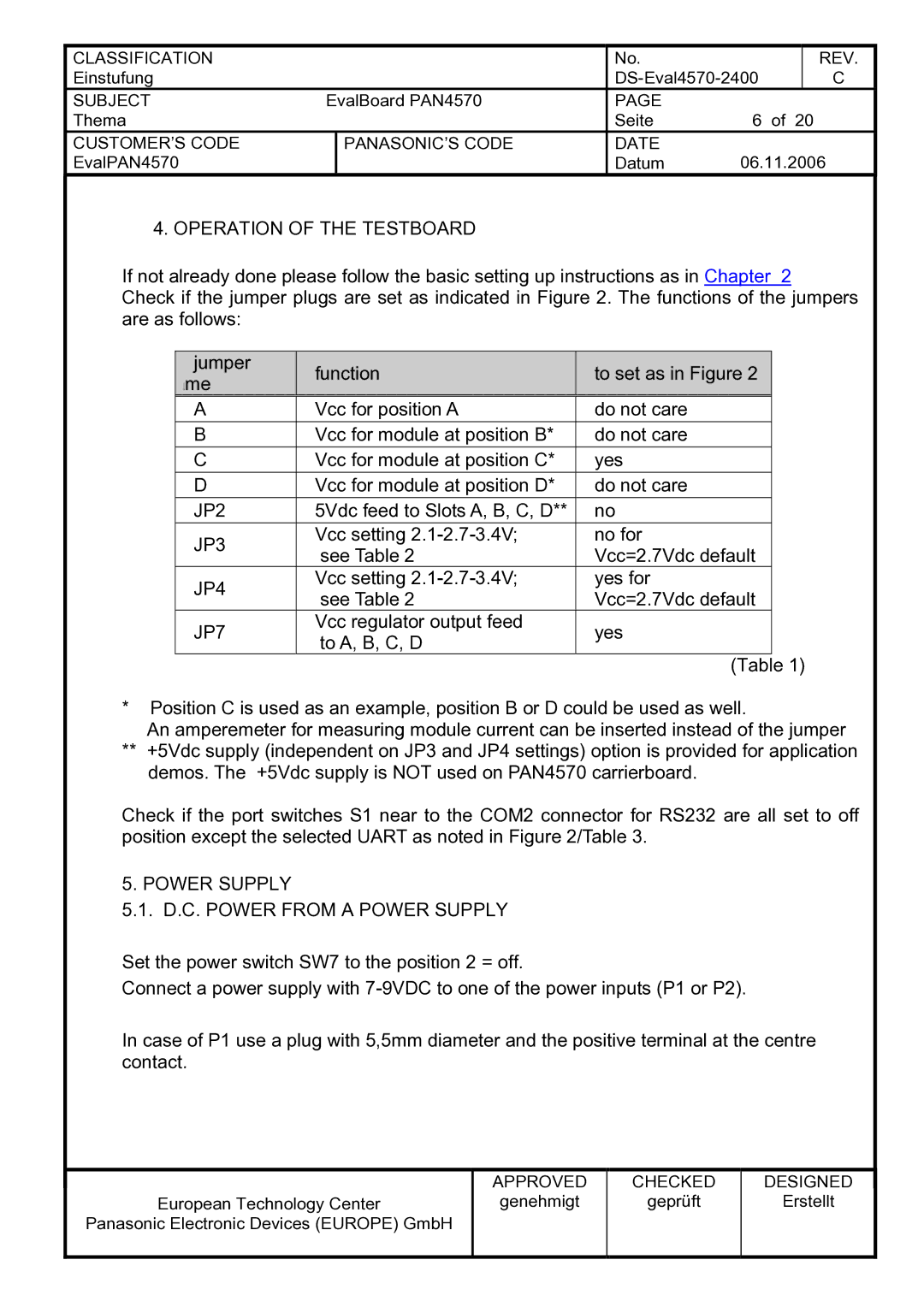
Check if the jumper plugs are set as indicated in Figure 2. The functions of the jumpers are as follows:
| jumper |
|
| function |
|
| to set as in Figure 2 |
|
|
| ame |
|
|
|
|
|
| ||
|
|
|
|
|
|
|
|
| |
| A |
|
| Vcc for position A |
| do not care |
| ||
| B |
|
| Vcc for module at position B* |
| do not care |
| ||
| C |
|
| Vcc for module at position C* |
| yes |
| ||
| D |
|
| Vcc for module at position D* |
| do not care |
| ||
| JP2 |
|
| 5Vdc feed to Slots A, B, C, D** |
| no |
| ||
| JP3 |
|
| Vcc setting |
| no for |
| ||
|
|
| see Table 2 |
| Vcc=2.7Vdc default |
| |||
|
|
|
|
|
| ||||
| JP4 |
|
| Vcc setting |
| yes for |
| ||
|
|
| see Table 2 |
| Vcc=2.7Vdc default |
| |||
|
|
|
|
|
| ||||
| JP7 |
|
| Vcc regulator output feed |
| yes |
| ||
|
|
| to A, B, C, D |
|
| ||||
|
|
|
|
|
|
| 1) | ||
|
|
|
|
|
|
| (Table | ||
*Position C is used as an example, position B or D could be used as well.
An amperemeter for measuring module current can be inserted instead of the jumper
**+5Vdc supply (independent on JP3 and JP4 settings) option is provided for application demos. The +5Vdc supply is NOT used on PAN4570 carrierboard.
Check if the port switches S1 near to the COM2 connector for RS232 are all set to off position except the selected UART as noted in Figure 2/Table 3.
5. POWER SUPPLY
5.1. D.C. POWER FROM A POWER SUPPLY
Set the power switch SW7 to the position 2 = off.
Connect a power supply with
In case of P1 use a plug with 5,5mm diameter and the positive terminal at the centre contact.
European Technology Center
Panasonic Electronic Devices (EUROPE) GmbH
APPROVED
genehmigt
CHECKED
geprüft
DESIGNED
Erstellt