For assistance, please call 1-888-VIEW-PTV843-9788
For assistance, please call
English
Trademarks
Risk of Electric Shock Do not Open
Important Safety Instructions
Dear Panasonic Customer
FCC Declaration of Conformity PT-52DL52
Table of Contents
Installation
AC Power Supply Cord Safety Precaution
Remote Control Battery Installation
Receiver Location
Installation
Precaution on battery use
Lamp unit replacement period
Replacing the lamp unit
Connecting the Aerial cable to the RF In Terminal
Antenna / Cable Connection
Incoming Cable from Home Antenna
Incoming Cable from Cable Company
Antenna Connection Cable Box, no VCR
Antenna Connection Cable Box, and VCR
How to connect the 1, 2, 3, 4 Input Terminals
How to connect the AV Prog. Out Terminals
Connects VCRs and other peripheral equipment
Video Audio
How to connect the Component Video Input Terminals
How to connect the Digital in Terminals
Connecting a DTV Decoder to Digital
Audio RCA plug
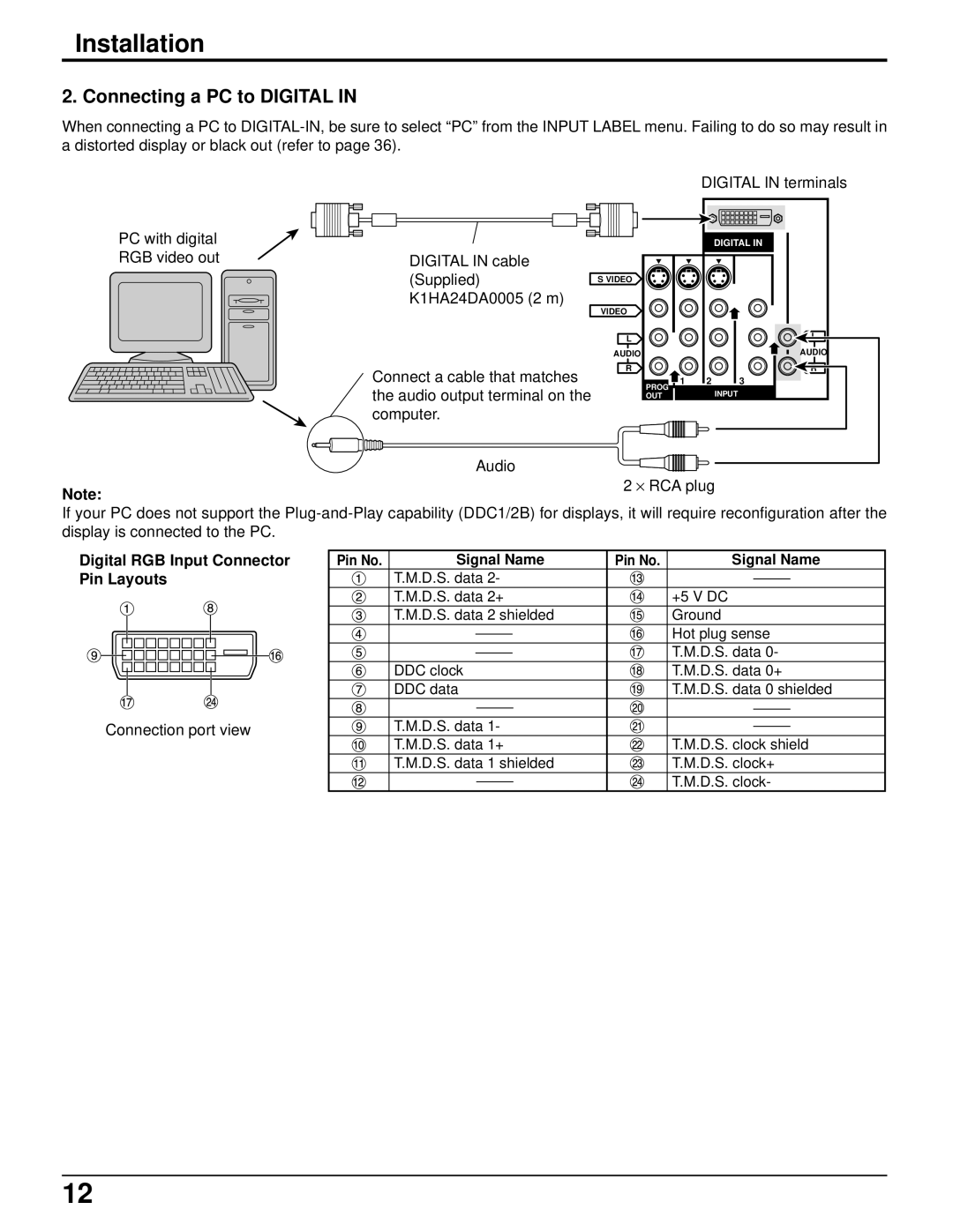
Connecting a PC to Digital
Digital RGB Input Connector Pin Layouts
Pin No Signal Name
How to connect the PC Input Terminals
Digital and analog RGB signals that can be input
Digital PC Input
Location of Controls
VCR
CABLE/DBS DVD/LD/CD
Rcvr
Location of Controls
Controls and Terminals on the Projection TV
Front
Rear
Prog out terminals See
Select the desired volume level
Cable TV / VHF, UHF and Catv
Cable TV VHF, UHF and Catv
Confirming
Power on / OFF
Connecting the Plug to the Wall Outlet
Turning the Power on and OFF
Power on / OFF
Power Indicator
Power ON/Off button
Menu Language Selection
Roller Guide Menu Navigation
Normal Picture
SET UP
Roller Guide Menu Navigation
SET UP Operation
SET UP
To end Adjustment
Menu Languages
Mode Selection
SET UP Operation
Antenna Selection
Cable
Auto Program
Manual Program
Auto Power
Chan Banner
SET OFF
Closed Captions
Cc on Mute
Cc Mode
Closed Captions
Text T1
Picture Adjustment
Picture Mode
Press to display the roller guide menu
Picture Adjustment
Color Tint Brightness Picture Sharpness Normal
Black EXT Video NR 3D Y/C Filter
Color Matrix
Freeze
Freeze
Split PIP
POS ADJ
Position
Clock Phase / DOT Clock
Clock Phase
Size
DOT Clock
Channel Scan
Channel Scan FAV
Channel Scan ALL
FAV ALL
Favorite Channels Selection
Channel
Use remote numeric keypad to
Select desired channel refer to
Your local TV guide
Label setting during DIGITAL-IN input mode
Caption
Audio Adjustment
Selecting STEREO/SAP/MONO
Audio Adjustment
Selecting Bass / Treble / Balance / Normal
AI Sound / BBE
Audio menu press to select Other ADJ
Surround
Speakers
OFF & Variable Audio OUT
OFF & Fixed Audio OUT
Picture in Picture Operation
Basic PIP Operation
Swap
Picture in Picture Operation
PIP MIN, PIP MAX
Freeze TV/VCR
TV/VIDEO Button
Split Screen
Splitting the screen
Freezing pictures
Aspect Switching
Split Screen
Changing the channels for the Split Screen
Viewing Videos
Aspect Controls
Aspect Aspect button
Zoom Full
Split Screen Normal Full
Timer
Clock SET
Timer1 and Timer2
Sleep
Enter Channel
YES
Lock Feature
Lock SET
Game
ALL
Lock Feature
OFF
Game
Always 48HOURS
Channel
ALL
Press to select channels
After finished with adjustments in the selected menu
Chip Menu Operation
TV Programs Rating Chart
TV Programs
Chip Menu Operation
Status
TV Programs Ratings Chart
TV-Y
TV-Y7
TV-G
Movies Rating Chart
Movies Ratings Chart
Movies
Canadian English Ratings Chart
Canadian English
C8+
14+
Canadian French Ratings Chart
Canadian French
Blocking Message
Split Screen Blocking Message
PIP Blocking Message
DTV
DBS
DVD/CD
AUX
Operating peripheral equipment using the remote control
Press Power and Action together, for at least
Seconds
After the code is found, press Action to store the code
Infrared Codes Index
Codes for VCR
Codes for Personal Video Recorders
Codes for DVD
Codes for CD
Codes for Cassette Deck
Codes for Receivers
Codes for Cable Box
Codes for DBS
ABC
Mode Operational Key Chart
KEY Name TV Mode DTV Mode Cable Mode DBS Mode
KEY Name VCR Mode DVD Mode AUX Mode Rcvr Mode
Troubleshooting Chart
Symptoms Checks
Cleaning
Specifications
Customer’s Record
Electric Corporation of America Puerto Rico Inc. PSC

