Service Adjustments and Calibrations |
1.2- Press “5” at the remote control to make appear a white line for screen calibration. In order to make tHe line disappear press “5” again.
DAC DIRECT TABLE
CHQ1 | CHQ2 | CHQ3 | CHQ4 | CHQ5 |
OP1 | HC | AFT | ||
OP2 | COR | VC | VID | |
OP3 | V ALT | RF | ||
OP4 | NITIDEZ | |||
OP5 | ||||
OP6 | CONTRAST | SUB BR | ||
BRIGHT | ||||
BRIGHT | ||||
MATIZ |
ELECTRICAL INSPECTION
1- EQUIPMENTS REQUIRED
1.1- High voltage meter, range to 30kv (eletrostatic or resistive)
1.2- Voltmeter, range 30VDC, 150 VDC and 300VAC
1.3- Voltmeter RMS
1.4- DY,CY,CRT
2- PREPARATION
2.1- Position controls on the following positions: NORMAL IMAGE……....…ADJUSTED
VOLUME………..........…… MINIMUM
TV/VIDEO……............…… TV
POT SCREEN…................CENTER
POT FOCUS…...........……BEST POINT ( VISUAL)
ENGLISH
MEMORY - DIRECT ACCESS METHOD
1.1- To obtain direct access to memory go to item CHQ1, press simultaneously VOL(_) at the TV set and “mute” at the remote control.
1.2- To alternate between memory positions press “3”or “4”. 1.3- To change the contents of each memory positions press VOL(+) or VOL(_), the letter will remain red. To memorize the changes press “0”, the letter will go
back to white.
1.4- To exit memory press “1” or “2” to alternate between the CHQ’s or press “N” to exit “SERVICE MODE” .
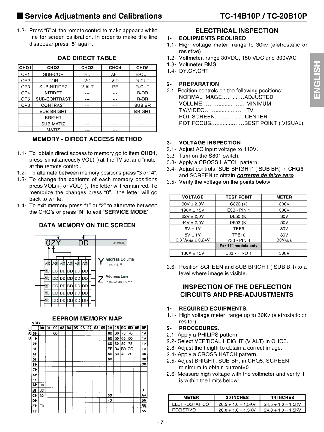
DATA MEMORY ON THE SCREEN
EEPROM MEMORY MAP
3- VOLTAGE INSPECTION
3.1- Adjust AC input voltage to 110V.
3.2- Turn on the S801 switch.
3.3- Apply a CROSS HATCH pattern.
3.4- Adjust controls “SUB BRIGHT” ( SUB BR) in CHQ5 and SCREEN to obtain corrente de feixe zero.
3.5- Verify the voltage on the points below:
VOLTAGE | TEST POINT | METER |
90V ± 2,0V | C823 (+) | 300V |
190V ± 15V | E33 - PIN 1 | 300V |
22V ± 2,0V | D850 (K) | 30V |
44V ± 2,5V | D852 (K) | 50V |
9V ± 1V | TPE9 | 30V |
5V ± 1V | TPE10 | 30V |
6,3 VRMS ± 0,24V | Y33 - PIN 4 | 30VRMS |
| For 14” models only |
|
180V ± 15V | E33 - PINO 1 | 300V |
3.6- Position SCREEN and SUB BRIGHT ( SUB BR) to a level where image is visible.
INSPECTION OF THE DEFLECTION CIRCUITS AND PRE-ADJUSTMENTS
1- REQUIRED EQUIPMENTS.
1.1- High voltage meter, range up to 30Kv (eletrostatic or resitor).
2- PROCEDURES.
2.1- Apply a PHILIPS pattern.
2.2- Select VERTICAL HEIGHT (V ALT) in CHQ3.
2.3- Adjust the heigth to obtain a correct image.
2.4- Apply a CROSS HATCH pattern.
2.5- Adjust BRIGHT, SUB BR, in CHQ5, SCREEN minimum to obtain current=0
2.6- Measure high voltage with the voltmeter and verify if is within the limits below:
METER | 20 INCHES | 14 INCHES |
ELETROSTÁTICO | 26,5 + 1,0 _ 1,5KV | 24,5 + 1,0 _ 1,5KV |
RESISTIVO | 26,0 + 1,0 _ 1,5KV | 24,0 + 1,0 _ 1,5KV |
- 7 -