Service Adjustments and Calibrations
NTSC | WHITE QUALITY CALIBRATION |
1. PREPARATION:
1.1.Connect the oscilloscope to TPL1 (R OUT) in serie with a 10KΩ resistor.
1.2.Receive a rainbow pattern through VIDEO IN.
1.3.Adjust “IMAGE” to DYNAMIC NORMAL.
1.4.Adjust “COLOR FOR CHANNEL” to NORMAL.
1.5.Set the CHK2 service mode option, press “5” on the remote control unit and confirm that OSD becomes blue (AKB turned off).
1.6.Connect a short circuit jumper between TPA10 and TPA20.
2. CALIBRATION:
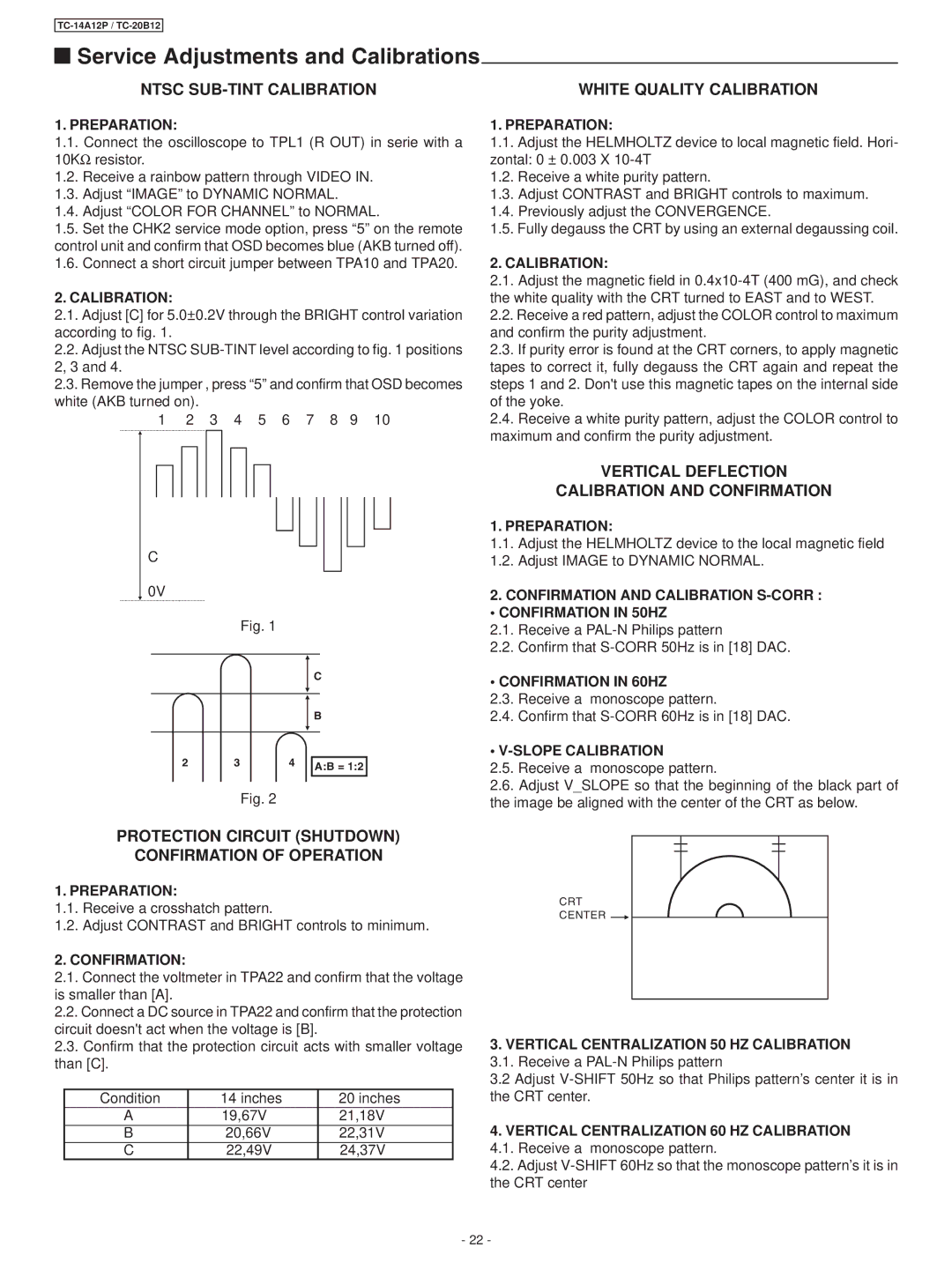
2.1.Adjust [C] for 5.0±0.2V through the BRIGHT control variation according to fig. 1.
2.2.Adjust the NTSC
2.3.Remove the jumper , press “5” and confirm that OSD becomes white (AKB turned on).
1 2 3 4 5 6 7 8 9 10
1. PREPARATION:
1.1.Adjust the HELMHOLTZ device to local magnetic field. Hori- zontal: 0 ± 0.003 X
1.2.Receive a white purity pattern.
1.3.Adjust CONTRAST and BRIGHT controls to maximum.
1.4.Previously adjust the CONVERGENCE.
1.5.Fully degauss the CRT by using an external degaussing coil.
2. CALIBRATION:
2.1.Adjust the magnetic field in
2.2.Receive a red pattern, adjust the COLOR control to maximum and confirm the purity adjustment.
2.3.If purity error is found at the CRT corners, to apply magnetic tapes to correct it, fully degauss the CRT again and repeat the steps 1 and 2. Don't use this magnetic tapes on the internal side of the yoke.
2.4.Receive a white purity pattern, adjust the COLOR control to maximum and confirm the purity adjustment.
C
0V
Fig. 1
C
B
2 | 3 | 4 | A:B = 1:2 |
|
|
|
Fig. 2
VERTICAL DEFLECTION
CALIBRATION AND CONFIRMATION
1. PREPARATION:
1.1.Adjust the HELMHOLTZ device to the local magnetic field
1.2.Adjust IMAGE to DYNAMIC NORMAL.
2.CONFIRMATION AND CALIBRATION
• CONFIRMATION IN 50HZ
2.1.Receive a
2.2.Confirm that
• CONFIRMATION IN 60HZ
2.3.Receive a monoscope pattern.
2.4.Confirm that
• V-SLOPE CALIBRATION
2.5.Receive a monoscope pattern.
2.6.Adjust V_SLOPE so that the beginning of the black part of the image be aligned with the center of the CRT as below.
PROTECTION CIRCUIT (SHUTDOWN)
CONFIRMATION OF OPERATION
1. PREPARATION:
1.1.Receive a crosshatch pattern.
1.2.Adjust CONTRAST and BRIGHT controls to minimum.
2. CONFIRMATION:
2.1.Connect the voltmeter in TPA22 and confirm that the voltage is smaller than [A].
2.2.Connect a DC source in TPA22 and confirm that the protection circuit doesn't act when the voltage is [B].
2.3.Confirm that the protection circuit acts with smaller voltage than [C].
Condition | 14 inches | 20 inches |
A | 19,67V | 21,18V |
B | 20,66V | 22,31V |
C | 22,49V | 24,37V |
CRT
CENTER 
3.VERTICAL CENTRALIZATION 50 HZ CALIBRATION
3.1.Receive a
3.2 Adjust
4.VERTICAL CENTRALIZATION 60 HZ CALIBRATION
4.1.Receive a monoscope pattern.
4.2.Adjust
- 22 -