Manuals
/
Panasonic
/
TV and Video
/
CRT Television
Panasonic
TC-14A12P, TC-20B12
service manual
Parts Location
Models:
TC-14A12P
TC-20B12
1
35
42
42
Download
42 pages
56.37 Kb
32
33
34
35
36
37
38
39
Troubleshooting
Install
IC601 Block Diagram
Configuration
IC601 Pins and Functions
Tuning Procedures
Auto Tuning Mode
Power Source Voltages
Features Menu
Channel Selection Mode
Page 35
Image 35
TC-14A12P /
TC-20B12
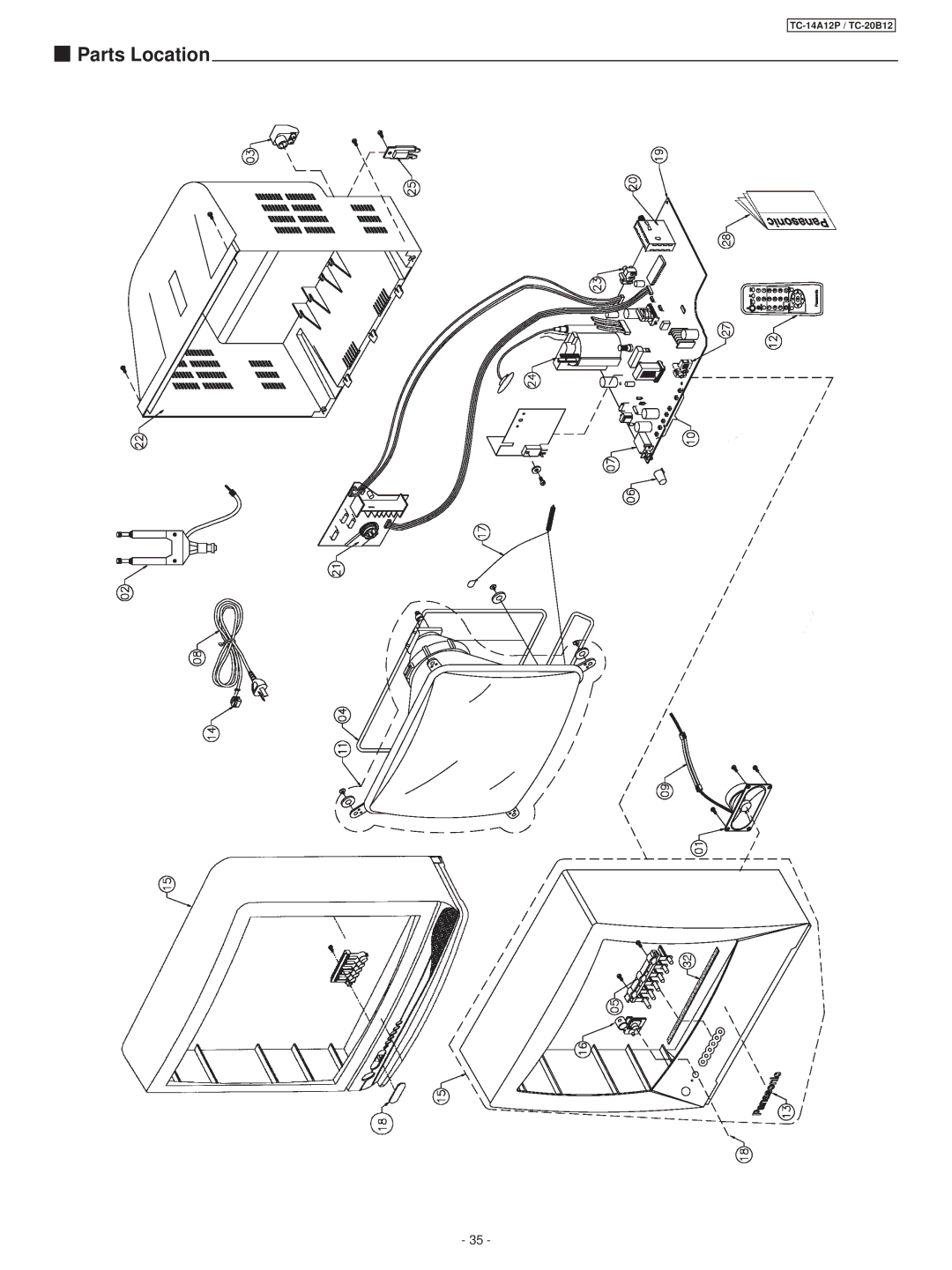
Parts Location
- 35 -
Page 34
Page 36
Page 35
Image 35
Page 34
Page 36
Contents
TC-14A12P TC-20B12
Contents
Back view
Operation Guide
Front view
Battery replacement precautions
Location of Controls Remote Control
Installing the Batteries
Outdoor Antenna Connection
Installation Operation of TV Controls
Connection
General Operation
WAKE-UP Button
Picture Menu Button
Tune Button
Main Menu Button
Channel Selection
Tuning Procedures
Main Menu List
Channel Capability
Channel Selection Mode
Antenna Mode
Operation
Manual Tune
Auto Tuning Mode
Manual Tuning Mode
Channe L
Fine Tuning Mode
Channel Skip Mode
Guide
Important Note
Supplementary Remote Control Operations
Color System Mode
Picture Menu
Sound Menu
Features Menu
No Ö C1 Language
Troubleshooting Chart
Hotel Mode
Cc on Mute Mute/Closed Caption
IC601 TDA9381PS/N2/3 Pins and Functions
Nome Descrição
IC601 Pins and Functions
Vddp
IC601 / IC451 Voltage Table
IC601 Block Diagram
General Summary
Configuration
Service Adjustments and Calibrations
Test Equipment
CRT Center
Ntsc SUB-TINT Calibration White Quality Calibration
CRT CUT OFF Calibration
Color Purity Adjustment Convergence Calibration
Power Source Voltages
Main Board Schematic Diagram TC-14A12P / TC-20B12
CRT Board Schematic Diagram
Main Board Conductor View left / component side
Main Board Conductor View right / component side
Main Board Conductor View left / foil side
Main Board Conductor View right / foil side
Waveform
TNR001
IC801
Parts Location
TC-20B12 TC-14A12P
Packing and Acessories Replacement Mechanical Parts List
Replacement Electrical Parts List
Diodo Chaveamento
MTZJT-7716A
MTZJT-7730D
MA152KTX Diodo Chaveamento SMD
ERG3FJ822H
Transistor DE Potência NPN
2SB792ATX Transistor SMD PNP 0,2 W
Transistor DE Potencia
ERDS1TJ223T
ERQ12HKR68P
ERQ12HJ1R5P
ERQ12HKR82P
Page
CS Group Technical Support
Top
Page
Image
Contents


 Parts Location