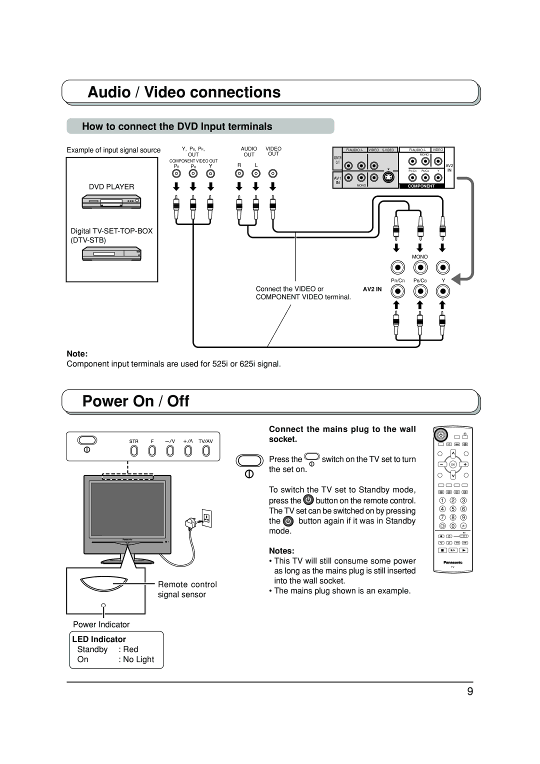
Audio / Video connections
How to connect the DVD Input terminals
Example of input signal source
DVD PLAYER
Digital
(DTV-STB)
| Y, PB, PR, |
| AUDIO | VIDEO | |
| OUT |
|
| OUT | OUT |
COMPONENT VIDEO OUT | R | L |
| ||
PR | PB | Y |
| ||
VIDEO |
| |||||
MONITOR |
|
|
| MONO |
|
|
|
|
|
|
|
| |
OUT |
|
|
|
|
| AV2 |
|
|
|
|
|
| |
|
|
| PR/CR | PB/CB | Y | IN |
AV1 |
|
|
|
|
|
|
IN |
|
| COMPONENT |
|
| |
MONO |
|
|
|
| ||
MONO
PR/CR PB/CB Y
Connect the VIDEO or | AV2 IN |
COMPONENT VIDEO terminal. |
|
Note:
Component input terminals are used for 525i or 625i signal.
Power On / Off
Remote control signal sensor
Power Indicator
LED Indicator
Standby | : Red |
On | : No Light |
Connect the mains plug to the wall socket.
Press the  switch on the TV set to turn the set on.
To switch the TV set to Standby mode, press the ![]() button on the remote control. The TV set can be switched on by pressing
button on the remote control. The TV set can be switched on by pressing
the ![]() button again if it was in Standby mode.
button again if it was in Standby mode.
Notes:
•This TV will still consume some power as long as the mains plug is still inserted into the wall socket.
•The mains plug shown is an example.
OK
1 2 3
4 5 6
7 8 9
0
TV
9
