SUPERSERVER
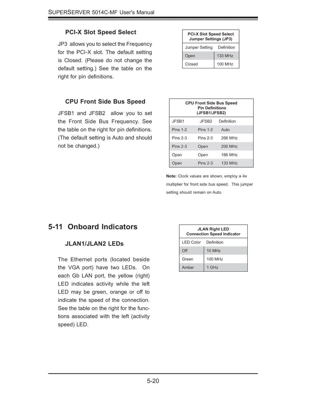
PCI-X Slot Speed Select
JP3 allows you to select the Frequency for the
CPU Front Side Bus Speed
JFSB1 and JFSB2 allow you to set the Front Side Bus Frequency. See the table on the right for pin defi nitions. (The default setting is Auto and should not be changed.)
Jumper Settings (JP3)
Jumper Setting | Defi nition | |
Open | 133 MHz | |
Closed | 100 MHz | |
|
|
CPU Front Side Bus Speed
Pin Definitions (JFSB1/JFSB2)
JFSB1 | JFSB2 | Defi nition |
Pins | Pins | Auto |
Pins | Pins | 266 MHz |
Pins | Open | 200 MHz |
Open | Open | 166 MHz |
Open | Pins | 133 MHz |
Note: Clock values are shown, employ a 4x multiplier for front side bus speed. This jumper setting should remain on Auto.
5-11 Onboard Indicators
JLAN1/JLAN2 LEDs
The Ethernet ports (located beside the VGA port) have two LEDs. On each Gb LAN port, the yellow (right) LED indicates activity while the left LED may be green, orange or off to indicate the speed of the connection. See the table on the right for the func- tions associated with the left (activity speed) LED.
JLAN Right LED
Connection Speed Indicator
LED Color | Defi nition | |
Off | 10 MHz | |
Green | 100 MHz | |
Amber | 1 GHz | |
|
|