Chapter 5: Advanced Motherboard Setup
Chassis Intrusion
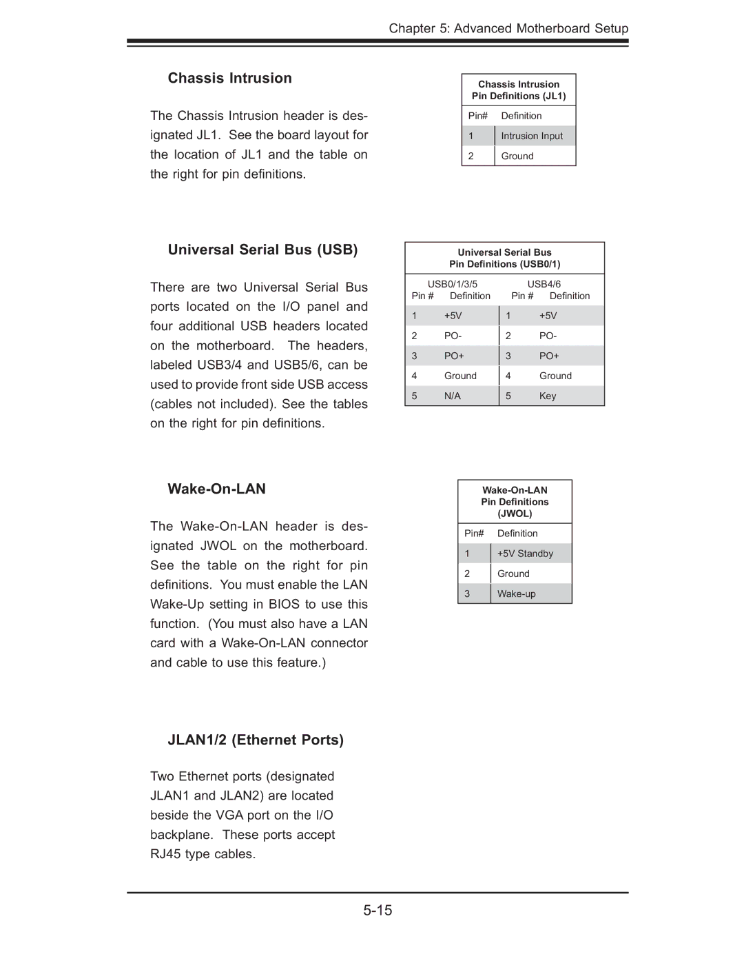
The Chassis Intrusion header is des- ignated JL1. See the board layout for the location of JL1 and the table on the right for pin defi nitions.
Chassis Intrusion
Pin Definitions (JL1)
Pin# Defi nition
1Intrusion Input
2Ground
Universal Serial Bus (USB)
Universal Serial Bus
Pin Definitions (USB0/1)
There are two Universal Serial Bus ports located on the I/O panel and four additional USB headers located on the motherboard. The headers, labeled USB3/4 and USB5/6, can be used to provide front side USB access (cables not included). See the tables on the right for pin defi nitions.
USB0/1/3/5 Pin # Defi nition
1+5V
2PO-
3PO+
4Ground
5N/A
USB4/6
Pin # Defi nition
1+5V
2PO-
3PO+
4Ground
5Key
Wake-On-LAN
The
JLAN1/2 (Ethernet Ports)
Two Ethernet ports (designated JLAN1 and JLAN2) are located beside the VGA port on the I/O backplane. These ports accept RJ45 type cables.
Pin Definitions
(JWOL)
Pin# Defi nition
1+5V Standby
2Ground
3
