SUPERSERVER
5-9 Connector
Definitions
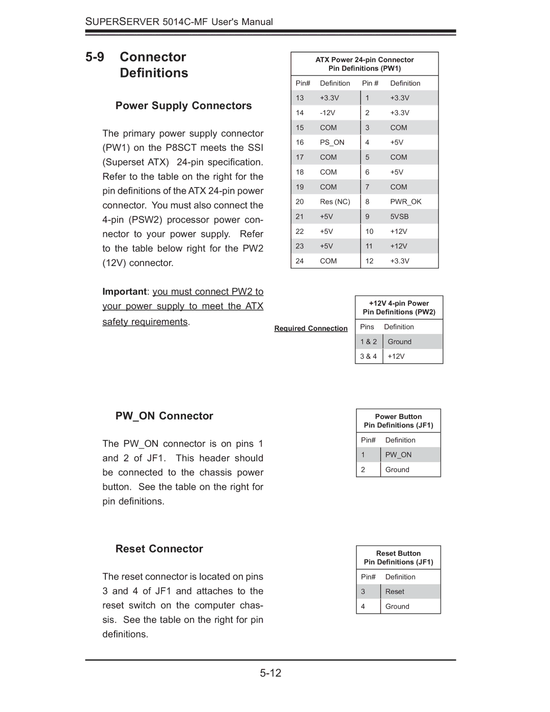
Power Supply Connectors
The primary power supply connector (PW1) on the P8SCT meets the SSI (Superset ATX)
ATX Power
Pin Definitions (PW1)
Pin# | Defi nition | Pin # | Defi nition | |
13 | +3.3V | 1 | +3.3V | |
14 |
| +3.3V | ||
2 | ||||
15 | COM |
| COM | |
3 | ||||
16 | PS_ON |
| +5V | |
4 | ||||
17 | COM |
| COM | |
5 | ||||
18 | COM |
| +5V | |
6 | ||||
19 | COM |
| COM | |
7 | ||||
20 | Res (NC) |
| PWR_OK | |
8 | ||||
21 | +5V |
| 5VSB | |
9 | ||||
22 | +5V | 10 | +12V | |
23 | +5V | 11 | +12V | |
24 | COM | 12 | +3.3V | |
|
|
|
|
Important: you must connect PW2 to your power supply to meet the ATX safety requirements.
Required Connection
PW_ON Connector
The PW_ON connector is on pins 1 and 2 of JF1. This header should be connected to the chassis power button. See the table on the right for pin defi nitions.
+12V
Pin Definitions (PW2)
Pins | Defi nition | |
1 & 2 | Ground | |
3 & 4 | +12V | |
|
|
Power Button
Pin Definitions (JF1)
Pin# Defi nition
1PW_ON
2 Ground
Reset Connector
The reset connector is located on pins 3 and 4 of JF1 and attaches to the reset switch on the computer chas- sis. See the table on the right for pin defi nitions.
Reset Button
Pin Definitions (JF1)
Pin# Defi nition
3Reset
4 Ground