SUPERSERVER
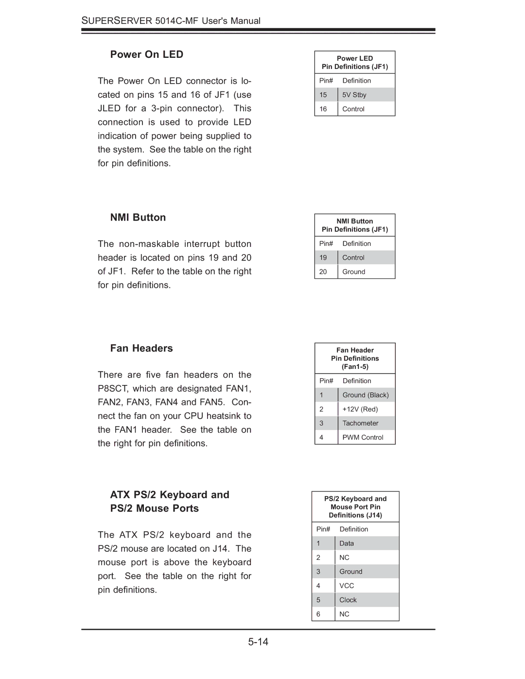
Power On LED
The Power On LED connector is lo- cated on pins 15 and 16 of JF1 (use JLED for a
NMI Button
The
Fan Headers
There are fi ve fan headers on the P8SCT, which are designated FAN1, FAN2, FAN3, FAN4 and FAN5. Con- nect the fan on your CPU heatsink to the FAN1 header. See the table on the right for pin defi nitions.
ATX PS/2 Keyboard and PS/2 Mouse Ports
The ATX PS/2 keyboard and the PS/2 mouse are located on J14. The mouse port is above the keyboard port. See the table on the right for pin defi nitions.
Power LED
Pin Definitions (JF1)
Pin# Defi nition
155V Stby
16Control
NMI Button
Pin Definitions (JF1)
Pin# Defi nition
19Control
20Ground
Fan Header
Pin Definitions
Pin# Defi nition
1Ground (Black)
2 +12V (Red)
3Tachometer
4PWM Control
PS/2 Keyboard and
Mouse Port Pin
Definitions (J14)
Pin# Defi nition
1Data
2NC
3Ground
4VCC
5Clock
6 NC