Chapter 5: Advanced Motherboard Setup
Overheat LED (OH)
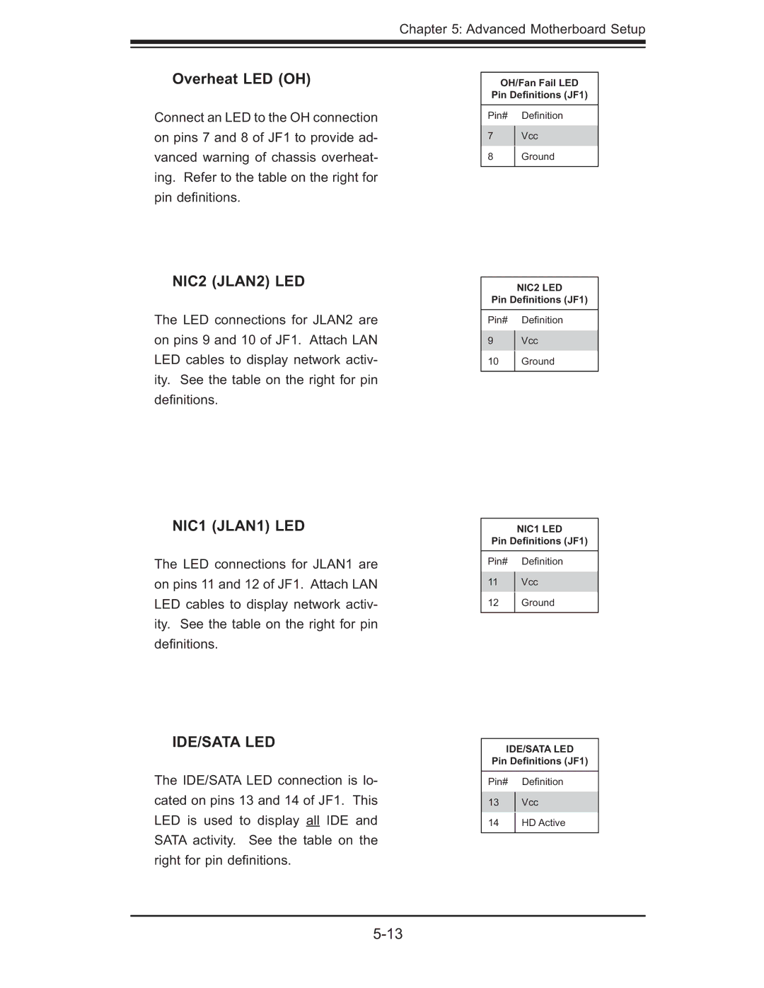
Connect an LED to the OH connection on pins 7 and 8 of JF1 to provide ad- vanced warning of chassis overheat- ing. Refer to the table on the right for pin defi nitions.
NIC2 (JLAN2) LED
The LED connections for JLAN2 are on pins 9 and 10 of JF1. Attach LAN LED cables to display network activ- ity. See the table on the right for pin defi nitions.
NIC1 (JLAN1) LED
The LED connections for JLAN1 are on pins 11 and 12 of JF1. Attach LAN LED cables to display network activ- ity. See the table on the right for pin defi nitions.
IDE/SATA LED
The IDE/SATA LED connection is lo- cated on pins 13 and 14 of JF1. This LED is used to display all IDE and SATA activity. See the table on the right for pin defi nitions.
OH/Fan Fail LED
Pin Definitions (JF1)
Pin# Defi nition
7Vcc
8Ground
NIC2 LED
Pin Definitions (JF1)
Pin# Defi nition
9Vcc
10 | Ground |
|
|
NIC1 LED
Pin Definitions (JF1)
Pin# Defi nition
11Vcc
12Ground
IDE/SATA LED
Pin Definitions (JF1)
Pin# Defi nition
13Vcc
14HD Active