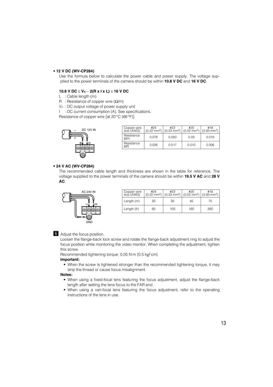
•12 V DC (WV-CP284)
Use the formula below to calculate the power cable and power supply. The voltage sup- plied to the power terminals of the camera should be within 10.8 V DC and 16 V DC.
10.8V DC ≤ VA − 2(R x I x L) ≤ 16 V DC
L : Cable length (m)
R : Resistance of copper wire (Ω/m)
VA : DC output voltage of power supply unit
I : DC current consumption (A). See specifications. Resistance of copper wire [at 20 °C {68 °F}]
–DC 12V IN
+
Copper wire | #24 | #22 | #20 | #18 | |
size (AWG) | (0.22 mm2) | (0.33 mm2) | (0.52 mm2) | (0.83 mm2) | |
Resistance | 0.078 | 0.050 | 0.03 | 0.018 | |
Ω/m | |||||
|
|
|
| ||
Resistance | 0.026 | 0.017 | 0.010 | 0.006 | |
Ω/ft | |||||
|
|
|
|
•24 V AC (WV-CP284)
The recommended cable length and thickness are shown in the table for reference. The voltage supplied to the power terminals of the camera should be within 19.5 V AC and 28 V AC.
AC 24V IN
1L | 2N |
Copper wire | #24 | #22 | #20 | #18 |
size (AWG) | (0.22 mm2) | (0.33 mm2) | (0.52 mm2) | (0.83 mm2) |
Length (m) | 20 | 30 | 45 | 75 |
|
|
|
|
|
Length (ft) | 65 | 100 | 160 | 260 |
|
|
|
|
|
GND
n Adjust the focus position.
Loosen the
Recommended tightening torque: 0.05 N·m {0.5 kgf·cm}
Important:
•When the screw is tightened stronger than the recommended tightening torque, it may strip the thread or cause focus misalignment.
Notes:
•When using a
•When using a
13