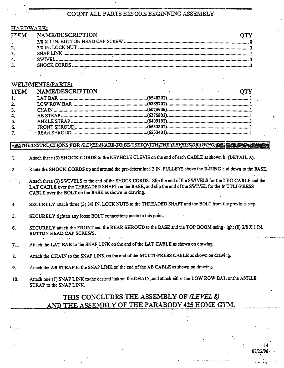
Y~EM
2.
3."
4.
CO .UNT ALL PARTS BEFORE BEGINNING ASSEMBLY |
| ||
¯ NA~ESCRIPTION |
| QTY | |
318X!INBLFFFON.HEADCAPSCKEW | 8 | ||
| |||
3/8INLOCK.~ | 3 | ||
~APL~ | : | l | |
| |||
S~L | ~ | ||
| |||
SHOCKCO~S | 3 | ||
.~ELDMENTS/PARTS: |
|
|
|
| |
ITEM | NAME/DESCRIPTION |
| QTY | ||
I. | LATBAR | : | ............................: (6540201) | 1 | |
2. | LOWROWBAR | (6389701) | 1 | ||
3. | CHAIN | (6075906) |
| ||
¯ 4. | ABSTRAP | : | (6375801) | 1 | |
5. | ANKLESTRAP | ~ | (6409101) | I | |
5. | FRONTSHROUD | (653330I) | ., | ||
| l | ||||
7. | " ' " | : | (65.33401) | : | .......1 |
|
|
| |||
I~KE~INSTRU.CTIiFOR(LE.O~S.~.L'..g);,ARE..T:O~BE:U.sED'~%~I..TH~ELfS:~TI~.7(LE.F,
I. Attach ~ree (3) SHOCKCORDSto the KEYHOLECLEVISon the end of each CABLE~ shown in (DETAILA).
2.Route the SHOCKCORDSup and around the
:Attach three (3) SWIVELSto the end of the S~OCKCORDSSlip. the end of the SWIVELSfor the LEGCABLE~mdthe
-LATCABLEover the THREADEDSHAFTon the BASE,and slip the end of the SWIVELfor the
4.SECURELYattach three (3) 3/8 IN. LOCKNUTSto the THREADEDSHAFTand ~he BOLTfrom the previous step. SECURELYtighten any loose BOLTconnections madeto this point:
| SECURELYattach the FRONTand the REARSHROUDto the BASEand the TOPBOOMusing eight (8) 3/8 X I IN. |
| BUTTON HEAD CAP SCREWS, |
| Attach the LATBARto the SNAPLINKon the end of the LATCABLEas shownon drawing. |
$. | Attach the CHAINto the SNAPLINKon the end of the |
9.A~tachthe A.B STRAPto the SNAPLINKon the end of the AB.CABLEas shownon drawing.
Attadh one (I) SNAPLiNK.to:thedesired.link on
THIS CONCLUDESTIlE ASSEMBLYOF (LEVEL 8)
AND THE ASSEMIBLY OF THE PAR.ABODY 425 HOMEGYM.
14
