THIS CONCLUDES TIIE ASSEMBLY OF (ZEFEL
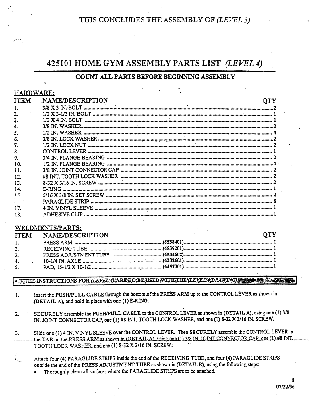
425101 HOMEGYMASSEMBLYPARTS LIST
COUNTALL PARTS BEFOREBEGINNI!NG ASSEMBLY
HARDWARE: |
|
|
|
|
|
| |
ITEM | .NAME/DESCRIPTION |
|
|
|
| QTY | |
| ¯ 318X'3IN..BOLT | ~ | : | ~ | 2 | ||
|
|
|
|
|
| ||
|
|
|
| ~ | 1 | ||
| 1/2X4IN.BOLT |
| ~: | " | ......................~ | , ..............1 | |
| 318IN.WASHER | ~...~ |
|
| 2 | ||
| 1/2IN.WASHER |
| ; |
| 4 | ||
| 3/8IN.LOCKWASHER | " " | 2 | " | 2 | ||
7. | 1/2_ IN. LOCKNUT |
| " , |
| 2 | ||
$. | CONTROL LEVER |
| ' |
|
|
| ,1 |
9. | 3/4 IN. FLANGEBEARING |
|
|
|
| 2 | |
I0. | I/2IN.FLANGEBEARING |
|
|
| ................................ 4 | ||
11. | 3/8l'N.JOINTCONNECTORCAP |
| : |
| 2 | ||
12. | #8INTTOOTH.LOCKWASHER | ' |
|
|
| : 2 | |
13. |
|
|
|
|
| 2 | |
14.E-KING...........................................................................................................
5/16X3/8IN.SETSCREW |
| 2 | ||
PARAGLIDESTRIP | ~ | 8 | ||
, | ||||
4IN.VINYLSLEEVE | ~ | 1 | ||
ADHESIVECLIP | ' | 1 | ||
WELDMENTS/PARTS: |
|
|
|
|
| |
ITEM | NAME/DESCRIPTION |
| " | QTY | ||
I. | PRESSARM |
|
| (6538401) | I | |
|
| (6539201) | 1 | |||
2. | RECEIVINGTUBE |
| ||||
3. | PRESSADJUSTMENTTUBE |
| (6534602) | I | ||
|
|
| ' I | |||
"4. |
| |||||
5. |
| ~ | ,: | (6457301) | 1 | |
| ............... |
|
| |||
I.Inse~t the PUSH/PULLCABLEthrough the bottom .oftheRRESSARMup to the
.(DETAILA), and hold in pla~e with one
2.SECURELYassemble the PUSH/PULLCABLEto the CONTROLLEVERas shown in (DETAILA), using one (1) IN. JOINTCONNECTORCAP, one (I) #8 INT. TOOTHLOCKWASHER,and one (1)
Slide one (I) IN. VI NYL SLEEVE over th e CONTROL LEVER. Then SECURELY sembleas th e CONTROL LEVER to
Attach four (4) PAPA.GLIDESTRIPSinside the end of the RECEIVINGTUBE,and four (4) PAPA.GLIDESTRIPS ou~ide the end of the PRESSADJUSTMENTTUBEas shownin (DETAILB), using the followin@steps:
¯Thoroughlyclean all surfaces wherethe PARAGLIDESTRIPSare to be attached.
07P_2~6