4
6
3/8 X 4” 60
7
64 | 5 |
2
54
FIGURE 7
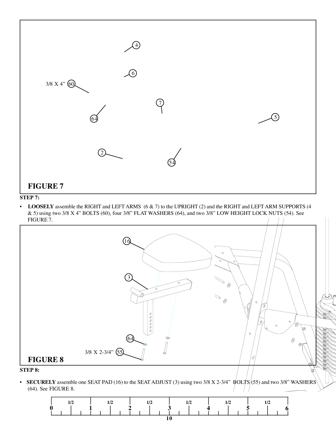
STEP 7:
•LOOSELY assemble the RIGHT and LEFT ARMS (6 & 7) to the UPRIGHT (2) and the RIGHT and LEFT ARM SUPPORTS (4 & 5) using two 3/8 X 4” BOLTS (60), four 3/8” FLAT WASHERS (64), and two 3/8” LOW HEIGHT LOCK NUTS (54). See FIGURE 7.
| 16 |
| 3 |
| 64 |
3/8 X | 55 |
FIGURE 8 |
|
STEP 8:
• SECURELY assemble one SEAT PAD (16) to the SEAT ADJUST (3) using two 3/8 X | ||||||
(64). See FIGURE 8. |
|
|
|
|
|
|
1/2 | 1/2 | 1/2 | 1/2 | 1/2 | 5 | 1/2 |
0 | 1 | 2 | 3 | 4 | 6 | |
|
|
| 10 |
|
|
|