1. Introduction
Front Panel
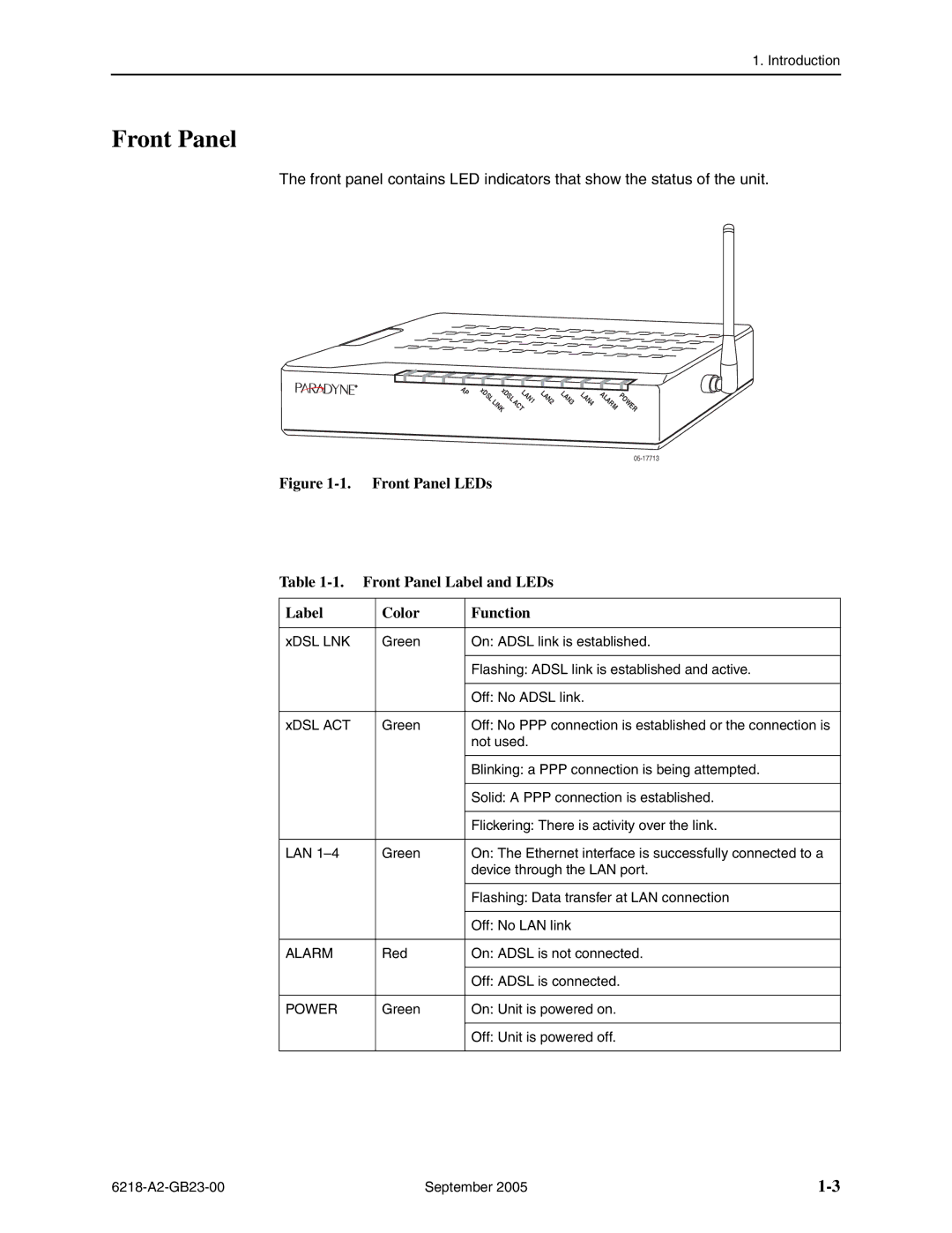
The front panel contains LED indicators that show the status of the unit.
AP | xDSL xDSL | LAN1 | LAN2 | LAN3 LAN4 ALARM |
| ||||
| LINK ACT |
| POWER | |
Figure 1-1. Front Panel LEDs
Table | Front Panel Label and LEDs | ||
|
|
|
|
Label |
| Color | Function |
|
|
|
|
xDSL LNK |
| Green | On: ADSL link is established. |
|
|
|
|
|
|
| Flashing: ADSL link is established and active. |
|
|
|
|
|
|
| Off: No ADSL link. |
|
|
|
|
xDSL ACT |
| Green | Off: No PPP connection is established or the connection is |
|
|
| not used. |
|
|
|
|
|
|
| Blinking: a PPP connection is being attempted. |
|
|
|
|
|
|
| Solid: A PPP connection is established. |
|
|
|
|
|
|
| Flickering: There is activity over the link. |
|
|
|
|
LAN |
| Green | On: The Ethernet interface is successfully connected to a |
|
|
| device through the LAN port. |
|
|
|
|
|
|
| Flashing: Data transfer at LAN connection |
|
|
|
|
|
|
| Off: No LAN link |
|
|
|
|
ALARM |
| Red | On: ADSL is not connected. |
|
|
|
|
|
|
| Off: ADSL is connected. |
|
|
|
|
POWER |
| Green | On: Unit is powered on. |
|
|
|
|
|
|
| Off: Unit is powered off. |
|
|
|
|
September 2005 |
