8 HD65 & HD130 STEPPER DRIVES USER GUIDE
1
24V
FAULT
ZERO
PHASE
BOOST
DIRN
CK
ENG
0V
SK1
9
18V SK2 | R1 | ||
0V |
| ||
18V |
| R2 | |
0V |
|
| |
ANTI |
|
| |
RES |
|
| |
SQ OFF | R29 | R3 R4 R5 R6 | |
EXT RESET | |||
|
| ||
SYNC
D1![]()
![]() D2
D2
8 | 16 | TP1 TP2 TP3 TP4 | ||
|
|
|
|
|
SYNC |
| SYNC | ||
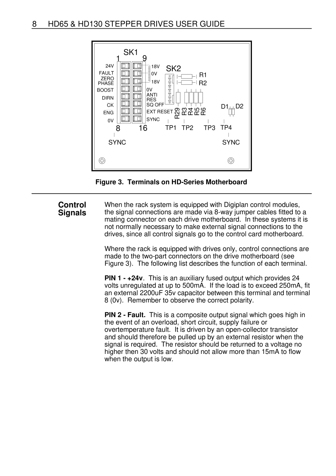
Figure 3. Terminals on HD-Series Motherboard
Control Signals
When the rack system is equipped with Digiplan control modules, the signal connections are made via
Where the rack is equipped with drives only, control connections are made to the
PIN 1 - +24v. This is an auxiliary fused output which provides 24 volts unregulated at up to 500mA. If the load is to exceed 250mA, fit an external 2200uF 35v capacitor between this terminal and terminal 8 (0v). Remember to observe the correct polarity.
PIN 2 - Fault. This is a composite output signal which goes high in the event of an overload, short circuit, supply failure or overtemperature fault. It is driven by an