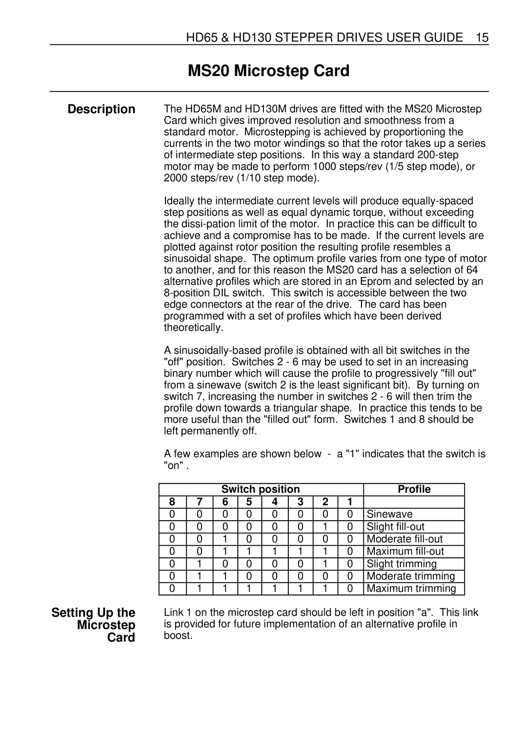
HD65 & HD130 STEPPER DRIVES USER GUIDE 15
MS20 Microstep Card
Description | The HD65M and HD130M drives are fitted with the MS20 Microstep | ||||||||||||
| Card which gives improved resolution and smoothness from a | ||||||||||||
| standard motor. Microstepping is achieved by proportioning the | ||||||||||||
| currents in the two motor windings so that the rotor takes up a series | ||||||||||||
| of intermediate step positions. In this way a standard | ||||||||||||
| motor may be made to perform 1000 steps/rev (1/5 step mode), or | ||||||||||||
| 2000 steps/rev (1/10 step mode). |
|
|
|
|
| |||||||
| Ideally the intermediate current levels will produce | ||||||||||||
| step positions as well as equal dynamic torque, without exceeding | ||||||||||||
| the | ||||||||||||
| achieve and a compromise has to be made. If the current levels are | ||||||||||||
| plotted against rotor position the resulting profile resembles a | ||||||||||||
| sinusoidal shape. The optimum profile varies from one type of motor | ||||||||||||
| to another, and for this reason the MS20 card has a selection of 64 | ||||||||||||
| alternative profiles which are stored in an Eprom and selected by an | ||||||||||||
| |||||||||||||
| edge connectors at the rear of the drive. The card has been | ||||||||||||
| programmed with a set of profiles which have been derived | ||||||||||||
| theoretically. |
|
|
|
|
|
|
|
|
| |||
| A | ||||||||||||
| "off" position. Switches 2 - 6 may be used to set in an increasing | ||||||||||||
| binary number which will cause the profile to progressively "fill out" | ||||||||||||
| from a sinewave (switch 2 is the least significant bit). By turning on | ||||||||||||
| switch 7, increasing the number in switches 2 - 6 will then trim the | ||||||||||||
| profile down towards a triangular shape. In practice this tends to be | ||||||||||||
| more useful than the "filled out" form. Switches 1 and 8 should be | ||||||||||||
| left permanently off. |
|
|
|
|
|
|
|
| ||||
| A few examples are shown below | - | a "1" indicates that the switch is | ||||||||||
| "on" . |
|
|
|
|
|
|
|
|
|
|
| |
|
|
|
|
|
|
|
|
|
|
|
|
|
|
|
|
|
| Switch position |
|
|
| Profile | |||||
| 8 |
| 7 | 6 | 5 | 4 | 3 |
| 2 |
| 1 |
|
|
| 0 |
| 0 | 0 | 0 | 0 | 0 |
| 0 |
| 0 | Sinewave |
|
| 0 |
| 0 | 0 | 0 | 0 | 0 |
| 1 |
| 0 | Slight |
|
| 0 |
| 0 | 1 | 0 | 0 | 0 |
| 0 |
| 0 | Moderate |
|
| 0 |
| 0 | 1 | 1 | 1 | 1 |
| 1 |
| 0 | Maximum |
|
| 0 |
| 1 | 0 | 0 | 0 | 0 |
| 1 |
| 0 | Slight trimming |
|
| 0 |
| 1 | 1 | 0 | 0 | 0 |
| 0 |
| 0 | Moderate trimming |
|
| 0 |
| 1 | 1 | 1 | 1 | 1 |
| 1 |
| 0 | Maximum trimming |
|
Setting Up the
Microstep
Card
Link 1 on the microstep card should be left in position "a". This link is provided for future implementation of an alternative profile in boost.
