14 HD65 & HD130 STEPPER DRIVES USER GUIDE
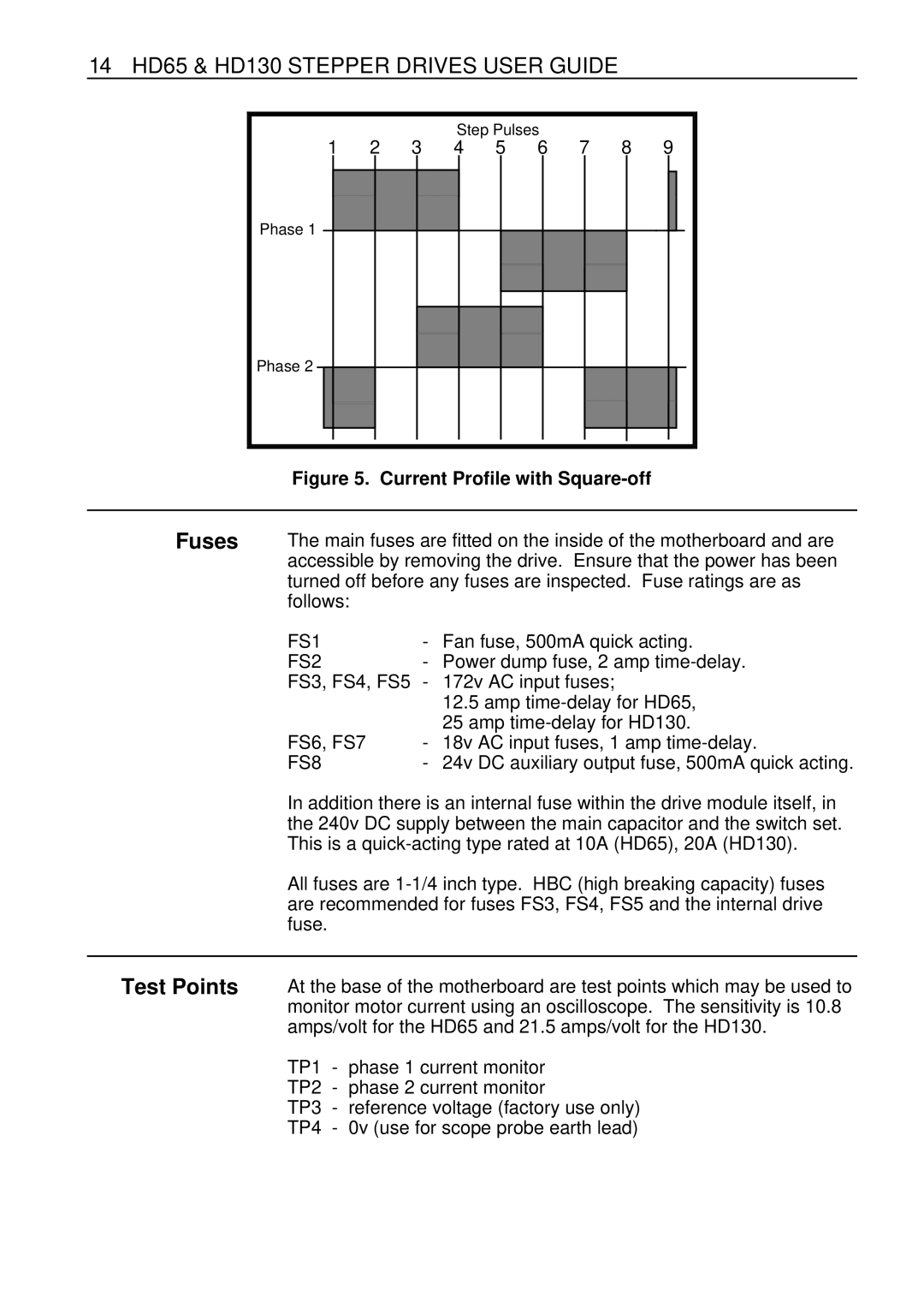
Step Pulses
1 | 2 | 3 | 4 | 5 | 6 | 7 | 8 | 9 |
Phase 1 |
Phase 2 |
Figure 5. Current Profile with Square-off
Fuses | The main fuses are fitted on the inside of the motherboard and are | |
| accessible by removing the drive. Ensure that the power has been | |
| turned off before any fuses are inspected. Fuse ratings are as | |
| follows: |
|
| FS1 | - Fan fuse, 500mA quick acting. |
| FS2 | - Power dump fuse, 2 amp |
| FS3, FS4, FS5 | - 172v AC input fuses; |
12.5amp
FS6, FS7 | - | 18v | AC input fuses, 1 amp |
FS8 | - | 24v | DC auxiliary output fuse, 500mA quick acting. |
In addition there is an internal fuse within the drive module itself, in the 240v DC supply between the main capacitor and the switch set. This is a
All fuses are
Test Points
At the base of the motherboard are test points which may be used to monitor motor current using an oscilloscope. The sensitivity is 10.8 amps/volt for the HD65 and 21.5 amps/volt for the HD130.
TP1 - phase 1 current monitor
TP2 - phase 2 current monitor
TP3 - reference voltage (factory use only)
TP4 - 0v (use for scope probe earth lead)