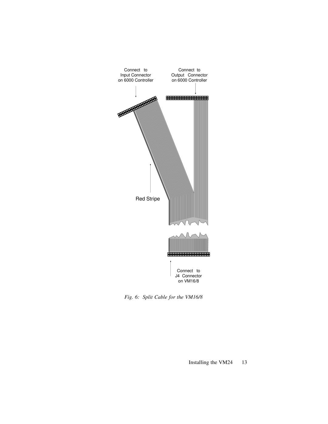
Manuals
/
Brands
/
Computer Equipment
/
Webcam
/
Parker Hannifin
/
Computer Equipment
/
Webcam
Parker Hannifin
vm24
- page 17
1
17
30
30
Download
30 pages, 358.72 Kb
Installing the VM24
13
Connect to
Output Connector
on 6000 Controller
Connect to
Input Connector
on 6000 Controller
Connect to
J4 Connector
on VM16/8
Red Stripe
Fig. 6: Split Cable for the VM16/8
Contents
Main
Compumotor
VM24 I/O Module
WARNING
Product Feedback Welcome
E-mail: 6000user@cmotor.com
Technical Assistance:
CONTENTS
Page
Page
2 VM24 I/O Module
What You Should Have (ship kit)
Overview VM24
Specification Summary
Parameter Specification
Page
Page
VM24 Assembly Configurations
8 VM24 I/O Module
I/O Pin Out Table
Electrical Connections
Page
Jumper Configuration
Ribbon Cable Connection
Page
Page
Installing the VM24 15
Input Connections
VM24
Remove power to the VM24 before making any connections.
Sinking
Out 5-24 Volts
Output Connections
Sinking
Electronic Device
+
VM24 6000 Series Controller
VM24 Module Configuration Summary
Page
Page
Basic Troubleshooting
6000 Series Controller/Indexer
Outputs:
Inputs:
50-pin Ribbon Cable
VM24
Power
Outputs
Inputs
SIM Board Insertion and Removal
To Insert I/O Boards
Page
VM24 I/O Module Pin Out Table