VM24 Assembly Configurations
The VM24 is available in five different configurations, as shown in the following table. Each configuration uses the same base unit. The combination of SIM boards installed in the base unit determine the I/O configuration.
Description | P/N | I/O Boards | Cable Type | |
|
|
|
|
|
Single Axis | VM24S | 2 | Regular | |
(16 IN / 8 OUT) |
| 1 |
| |
24 IN | VM24IN | 3 | Regular | |
24 OUT | VM24OUT | 3 | Regular | |
16 IN/8 OUT | VM16/8 | 1 | Split | |
|
| 2 |
| |
8 IN / 16 OUT | VN8/16 | 1 | Split | |
|
| 2 |
| |
|
|
|
|
|
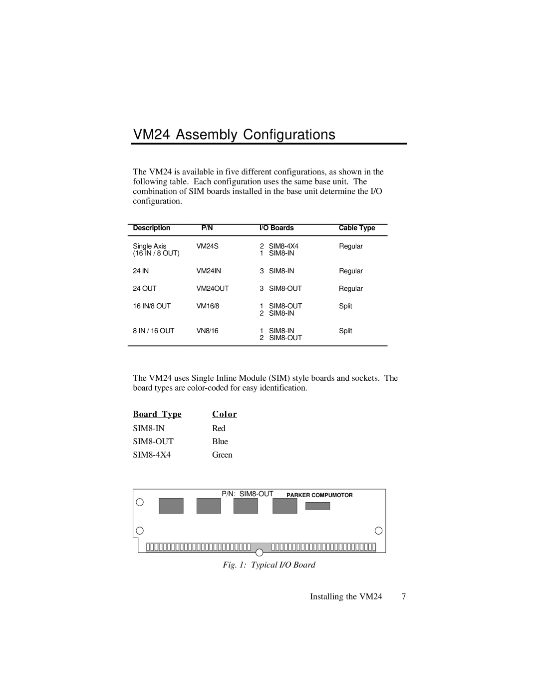
The VM24 uses Single Inline Module (SIM) style boards and sockets. The board types are
Board Type | Color |
P/N:
Fig. 1: Typical I/O Board
Installing the VM24 | 7 |