Modu-Fire® Gas-Fired Boiler
Configuration Level
The configuration level is used to set up the control for the sensors used, and the functioning of the alarm relay. The configuration level must be ad- justed by
3.12.1B Optional Remote Control
This option is used when the firing rate of the boiler is controlled by an external analog signal, usually from a multiple boiler control. The boiler turns on and off as directed by the external control.
An operating limit control ensures that the boiler temperature does not exceed the set value.
Remote/ | Firing Rate |
Local |
|
Remote/Local and Firing Rate Switches
Local control is used for setting up and testing the boiler. Local control of the boiler firing rate can be obtained by placing the Remote/Local switch in the local position (This does not bypass # 1 start inter- lock, # 1 start interlock must be made for the boiler to fire). With the boiler in local mode, the up/down switch can be used to control the firing rate of the boiler. Pressing this switch in the up direction in- creases the firing rate. Placing this switch in the down position decreases the firing rate.
To operate the boiler independently from the BMS (Building Management System) or sequencer, an external bypass switch of the BMS must be installed by the control contractor.
WARNING!
Do not bypass any safety limits with this switch.
Installation
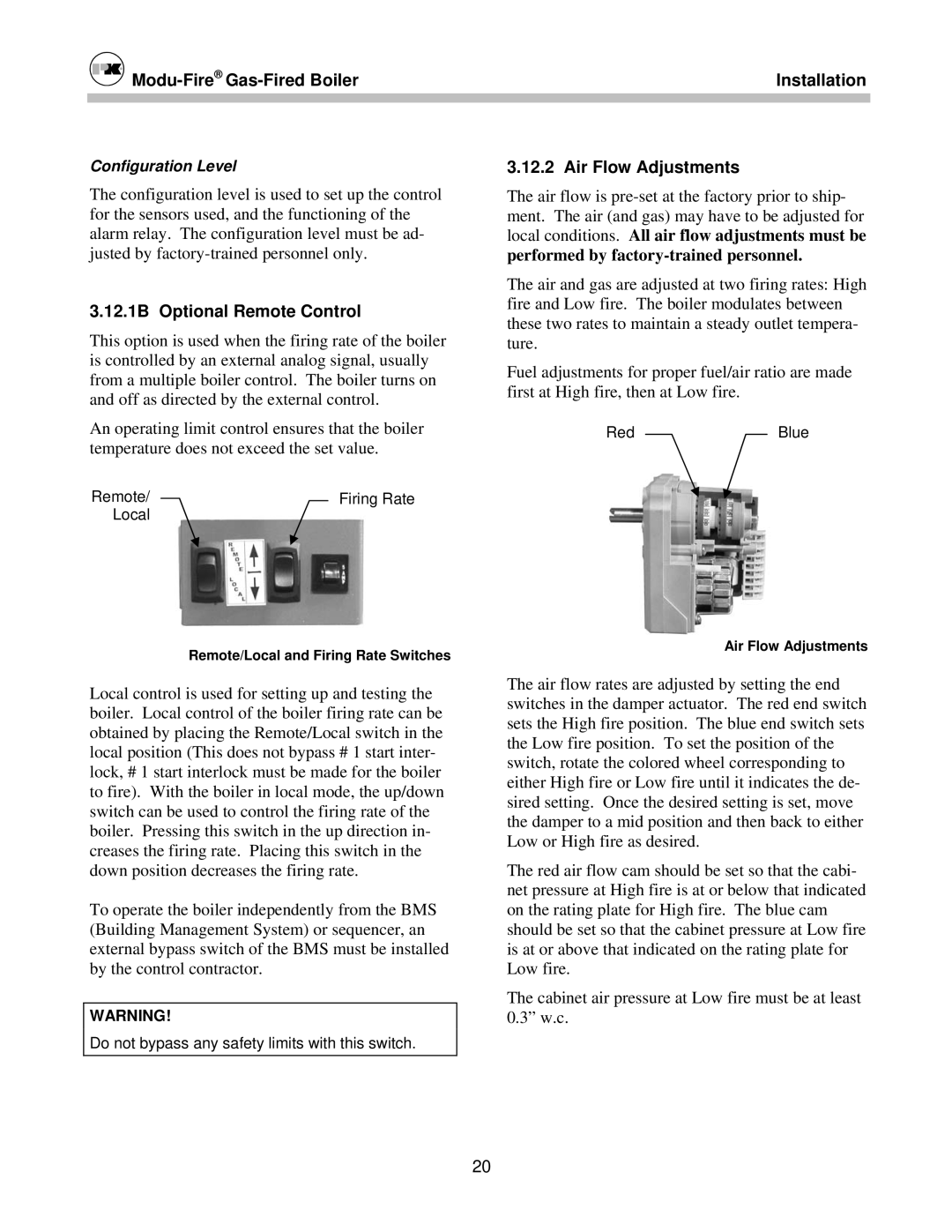
3.12.2 Air Flow Adjustments
The air flow is
The air and gas are adjusted at two firing rates: High fire and Low fire. The boiler modulates between these two rates to maintain a steady outlet tempera- ture.
Fuel adjustments for proper fuel/air ratio are made first at High fire, then at Low fire.
RedBlue
Air Flow Adjustments
The air flow rates are adjusted by setting the end switches in the damper actuator. The red end switch sets the High fire position. The blue end switch sets the Low fire position. To set the position of the switch, rotate the colored wheel corresponding to either High fire or Low fire until it indicates the de- sired setting. Once the desired setting is set, move the damper to a mid position and then back to either Low or High fire as desired.
The red air flow cam should be set so that the cabi- net pressure at High fire is at or below that indicated on the rating plate for High fire. The blue cam should be set so that the cabinet pressure at Low fire is at or above that indicated on the rating plate for Low fire.
The cabinet air pressure at Low fire must be at least 0.3” w.c.
20