
Modu-Fire® Gas-Fired Boiler
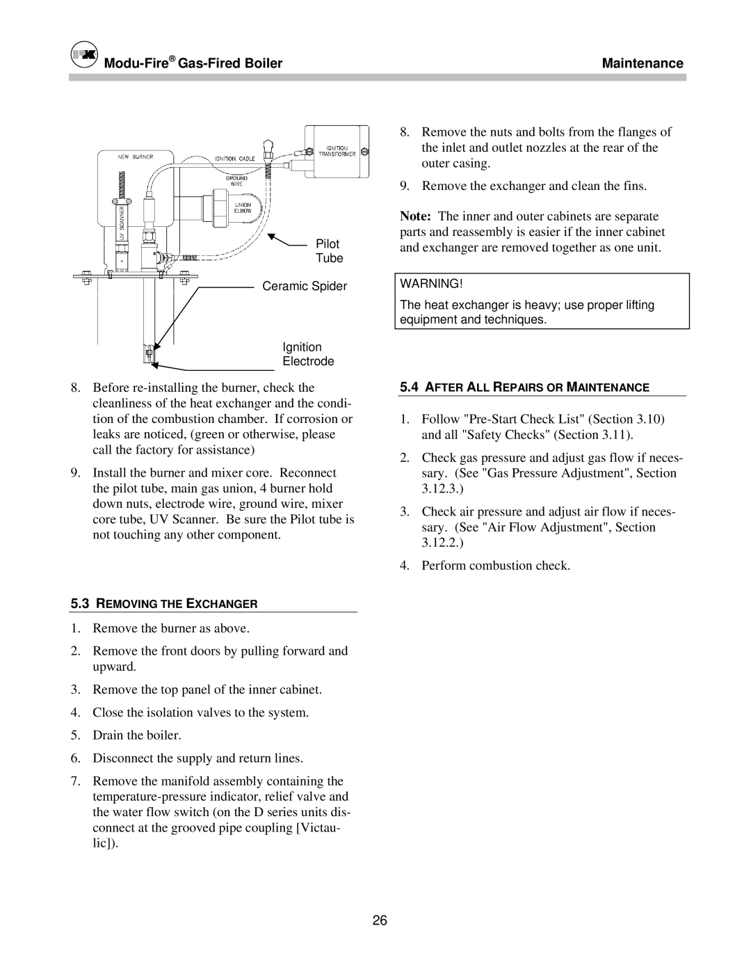
Pilot
Tube
Ceramic Spider
Ignition
Electrode
8.Before
9.Install the burner and mixer core. Reconnect the pilot tube, main gas union, 4 burner hold down nuts, electrode wire, ground wire, mixer core tube, UV Scanner. Be sure the Pilot tube is not touching any other component.
5.3REMOVING THE EXCHANGER
1.Remove the burner as above.
2.Remove the front doors by pulling forward and upward.
3.Remove the top panel of the inner cabinet.
4.Close the isolation valves to the system.
5.Drain the boiler.
6.Disconnect the supply and return lines.
7.Remove the manifold assembly containing the
Maintenance
8.Remove the nuts and bolts from the flanges of the inlet and outlet nozzles at the rear of the outer casing.
9.Remove the exchanger and clean the fins.
Note: The inner and outer cabinets are separate parts and reassembly is easier if the inner cabinet and exchanger are removed together as one unit.
WARNING!
The heat exchanger is heavy; use proper lifting equipment and techniques.
5.4AFTER ALL REPAIRS OR MAINTENANCE
1.Follow
2.Check gas pressure and adjust gas flow if neces- sary. (See "Gas Pressure Adjustment", Section 3.12.3.)
3.Check air pressure and adjust air flow if neces- sary. (See "Air Flow Adjustment", Section 3.12.2.)
4.Perform combustion check.
26
