4.0 INSTALLATION
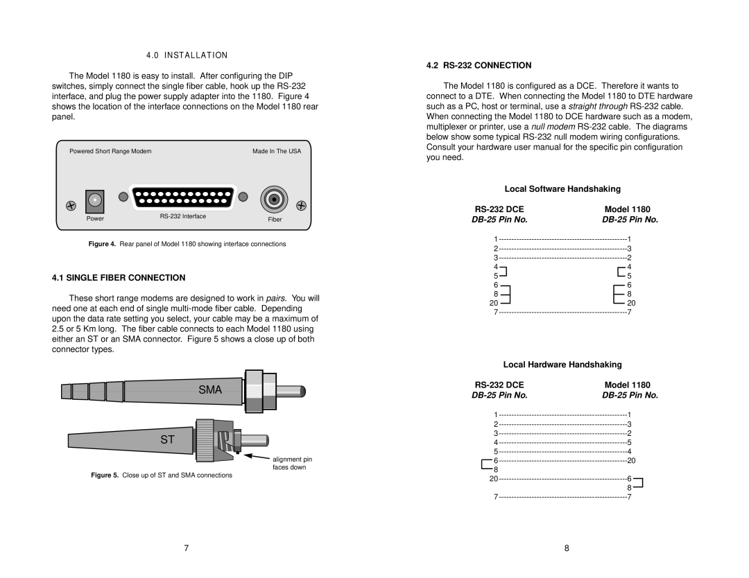
The Model 1180 is easy to install. After configuring the DIP switches, simply connect the single fiber cable, hook up the
Powered Short Range Modem | Made In The USA |
Power | Fiber | |
|
Figure 4. Rear panel of Model 1180 showing interface connections
4.1 SINGLE FIBER CONNECTION
These short range modems are designed to work in pairs. You will need one at each end of single
2.5or 5 Km long. The fiber cable connects to each Model 1180 using either an ST or an SMA connector. Figure 5 shows a close up of both connector types.
SMA
ST
![]() alignment pin faces down
alignment pin faces down
Figure 5. Close up of ST and SMA connections
4.2 RS-232 CONNECTION
The Model 1180 is configured as a DCE. Therefore it wants to connect to a DTE. When connecting the Model 1180 to DTE hardware such as a PC, host or terminal, use a straight through
Local Software Handshaking
| Model 1180 | |||||||||||||
1 |
|
|
|
|
| 1 | ||||||||
2 |
|
|
|
|
| 3 | ||||||||
3 |
|
|
|
|
| 2 | ||||||||
4 |
|
|
|
|
|
|
|
|
|
|
|
|
| 4 |
|
|
|
|
|
|
|
|
|
|
|
|
| ||
5 |
|
|
|
|
|
|
|
|
|
|
|
| 5 | |
|
|
|
|
|
|
|
|
|
|
|
| |||
6 |
|
|
|
|
|
|
|
|
|
| 6 | |||
|
|
|
|
|
|
|
|
|
| |||||
8 |
|
|
|
|
|
|
|
| 8 | |||||
|
|
| ||||||||||||
20 |
|
|
|
|
|
|
|
| 20 | |||||
|
|
|
| |||||||||||
7 |
|
|
|
|
| 7 | ||||||||
Local Hardware Handshaking
| Model 1180 | ||||||
1 | 1 |
|
|
| |||
2 | 3 |
|
|
| |||
3 | 2 |
|
|
| |||
4 | 5 |
|
|
| |||
5 | 4 |
|
|
| |||
|
| 6 | 20 |
| |||
| |||||||
|
| 8 |
|
|
|
| |
|
|
|
|
| |||
20 | 6 |
|
|
| |||
|
|
| |||||
|
|
|
| 8 |
|
|
|
|
|
|
|
|
|
| |
7 | 7 |
|
|
| |||
7 | 8 |
