5.0 OPERATION
Once you have configured each Model 1180 properly (see Section
3.0) and connected the fiber and
5.1 LED STATUS MONITORS
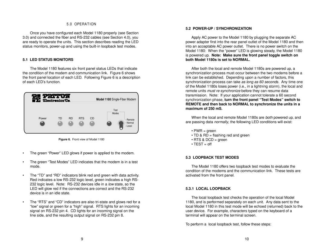
The Model 1180 features six front panel status LEDs that indicate the condition of the modem and communication link. Figure 6 shows the front panel location of each LED. Following Figure 6 is a description of each LED’s function.
Model 1180
Test
Modes
Power | TD | RD RTS CD | - Remote |
|
|
| |
|
|
| - Normal |
|
|
| - Local |
Figure 6. Front view of Model 1180
•The green “Power” LED glows if power is applied to the modem.
•The green “Test Modes” LED indicates that the modem is in a test mode.
•The “TD” and “RD” indicatorslinkb red and green with data activity. Red indicates a low
•The “RTS” and “CD” indicators are also
5.2 POWER-UP / SYNCHRONIZATION
Apply AC power to the Model 1180 by plugging the separate AC power adapter first into the rear panel outlet of the Model 1180 and then into an acceptable AC power outlet. There is no power switch on the Model 1180: When the “power” LED is glowing steady, the Model 1180 is powered up. Note: Make sure the front panel toggle switch on both Model 1180s is set to NORMAL.
After both the local and remote Model 1180s are powered up, a synchronization process must occur between the two modems before a link can be established. Depending upon a number of factors, this synchronization process can take as long as 60 seconds. Any time one of the Model 1180s loses power (i.e., in a lightning storm), the local and remote units must
REMOTE and then back to NORMAL to synchronize the units in a maximum of 250 mS.
When the local and remote Model 1180s are both powered up, and are passing data normally, the following LED conditions will exist:
•PWR = green
•TD & RD = flashing red and green
•RTS & DCD = green
•TEST = off
5.3LOOPBACK TEST MODES
The Model 1180 offers two loopback test modes to evaluate the condition of the modems and the communication link. These tests are activated from the front panel.
5.3.1 LOCAL LOOPBACK
The local loopback test checks the operation of the local Model 1180, and is performed separately on each unit. Any data sent to the local Model 1180 in this test mode will be echoed (returned) back to the user device. For example, characters typed on the keyboard of a terminal will appear on the terminal screen.
To perform a local loopback test, follow these steps:
9 | 10 |