lations and decodes them as zeros. This method enables the net- work to meet minimum pulse density requirements. Use HDB3 unless AMI is required in your application.

Alternate Mark Inversion (AMI): AMI defines a pulse as a Òmark,Ó a binary one, as opposed to a zero. In an E1 Network con- nection, signals are transmitted as a sequence of ones and zeros. Ones are sent as pulses, and zeros are sent as spaces, i.e., no pulse. Every other pulse is inverted from the previous pulse in polarity, so that the signal can be effectively transmitted. This means, however, that a long sequence of zeros in the data stream will cause problems, since the modem receiving the signal relies on the signal to recover the 2.048 Mbps clock.

If you must use AMI, ensure that the data terminal equipment con- nected to the unit provides a minimally acceptable pulse density. For this reason, there are advantages to using HDB3 instead. AMI coding does not inherently account for ones density. To meet this requirement, ensure that the data inherently meets pulse density requirements.

S3

S4

DTE Line Coding

Off

Off

HDB3

On

Off

Internal use only

Off

On

Internal use only

On

On

AMI

Switches S5 through S8: Reserved

Switches S5 through S8 are reserved for future applications and should be set to OFF.

3.1.2 Select RJ-48C or BNC Connectors

The Model 1193 is shipped configured for use with a BNC connec- tion to the G.703/G.704 Network. If your Network connection is using BNC, skip this section.

7

Jumper Configuration

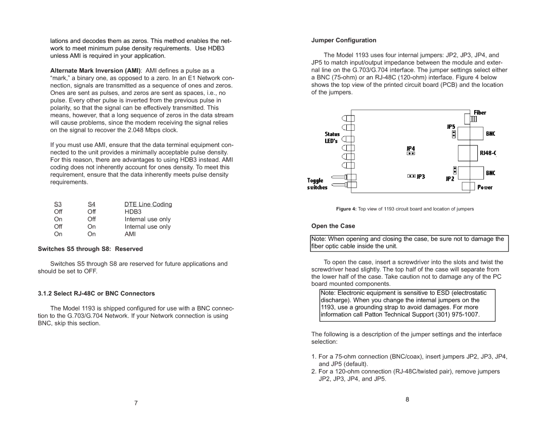
The Model 1193 uses four internal jumpers: JP2, JP3, JP4, and JP5 to match input/output impedance between the module and exter- nal line on the G.703/G.704 interface. The jumper settings select either a BNC (75-ohm) or an RJ-48C (120-ohm) interface. Figure 4 below shows the top view of the printed circuit board (PCB) and the location of the jumpers.

Figure 4: Top view of 1193 circuit board and location of jumpers

Open the Case

Note: When opening and closing the case, be sure not to damage the fiber optic cable inside the unit.

To open the case, insert a screwdriver into the slots and twist the screwdriver head slightly. The top half of the case will separate from the lower half of the case. Take caution not to damage any of the PC board mounted components.

Note: Electronic equipment is sensitive to ESD (electrostatic discharge). When you change the internal jumpers on the 1193, use a grounding strap to avoid damages. For more information call Patton Technical Support (301) 975-1007.

The following is a description of the jumper settings and the interface selection:

1.For a 75-ohm connection (BNC/coax), insert jumpers JP2, JP3, JP4, and JP5 (default).

2.For a 120-ohm connection (RJ-48C/twisted pair), remove jumpers JP2, JP3, JP4, and JP5.

8

Page 5
Image 5
Patton electronic 1193 user manual Switches S5 through S8 Reserved, Select RJ-48C or BNC Connectors, Jumper Configuration

1193 specifications

The Patton Electronics 1193 is a versatile and robust standalone device recognized for its efficacy in connecting serial devices over IP networks. Designed for both enterprise and industrial applications, it features a user-friendly interface and a set of capabilities that cater to various communication requirements.

One of the primary features of the Patton 1193 is its serial-to-IP conversion, which allows seamless communication between legacy serial devices and modern Ethernet networks. This capability is invaluable for businesses looking to integrate older technologies into contemporary systems without incurring the costs of complete hardware replacements. The device supports multiple serial protocols, including RS-232, RS-422, and RS-485, ensuring that it can interface with a wide range of equipment.

The Patton 1193 boasts advanced security features to protect data integrity during transmission. With built-in SSL/TLS encryption, the device helps safeguard sensitive information from unauthorized access and cyber threats. This is critical in environments such as SCADA systems where data security is paramount. Moreover, the Patton 1193 offers remote access and management capabilities, allowing users to configure and monitor the device from anywhere, which enhances operational efficiency.

In terms of connectivity, the Patton 1193 is equipped with dual Ethernet ports for network redundancy and supports Power over Ethernet (PoE). This feature simplifies installation and helps reduce the number of cables required, making it easier to deploy in locations without proximity to power outlets. The physical design of the device allows for wall or rackmount installation, providing flexibility in how it can be integrated into existing infrastructure.

The device also includes a web-based management interface, making configuration straightforward even for users with limited technical expertise. Users can quickly set up parameters, monitor performance metrics, and update firmware as necessary to ensure the device operates at optimal capacity.

Another appealing aspect of the Patton 1193 is its durability and reliability. Constructed to withstand harsh environmental conditions, such as extreme temperatures and electrical interference, it is an ideal choice for deployments in factories, transportation hubs, and outdoor settings. As industries increasingly rely on automation and data-driven decision-making, the Patton 1193 serves as a critical link, enabling the integration of diverse systems and ensuring continuous connectivity across various environments.