4.0 OPERATION
Once the CopperLink Ethernet Extenders are properly installed, they should operate transparently. No user settings required. This section describes reading the LED status monitors.
4.1 FRONT PANEL LED STATUS MONITORS
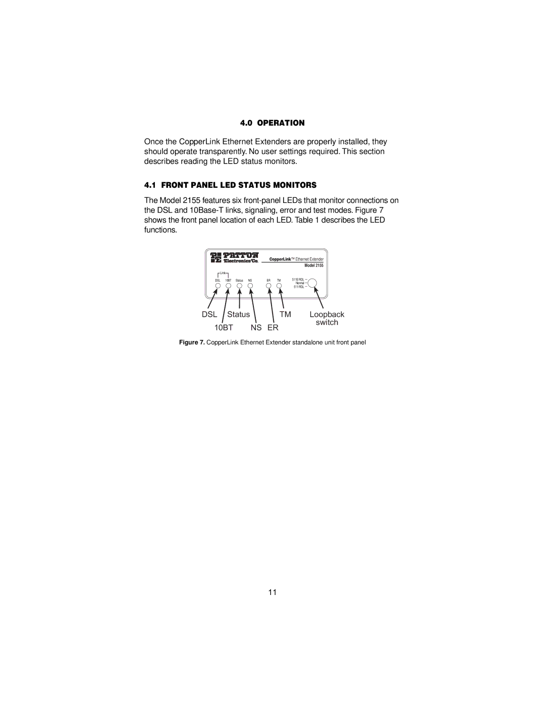
The Model 2155 features six
CopperLink™ Ethernet Extender
Model 2155
Link |
|
|
| |
DSL 10BT Status NS | ER | TM | 511E/RDL | |
Normal | ||||
|
|
| ||
|
|
| 511/RDL |
DSL Status | TM | Loopback |
10BT | NS ER | switch |
|
Figure 7. CopperLink Ethernet Extender standalone unit front panel
11