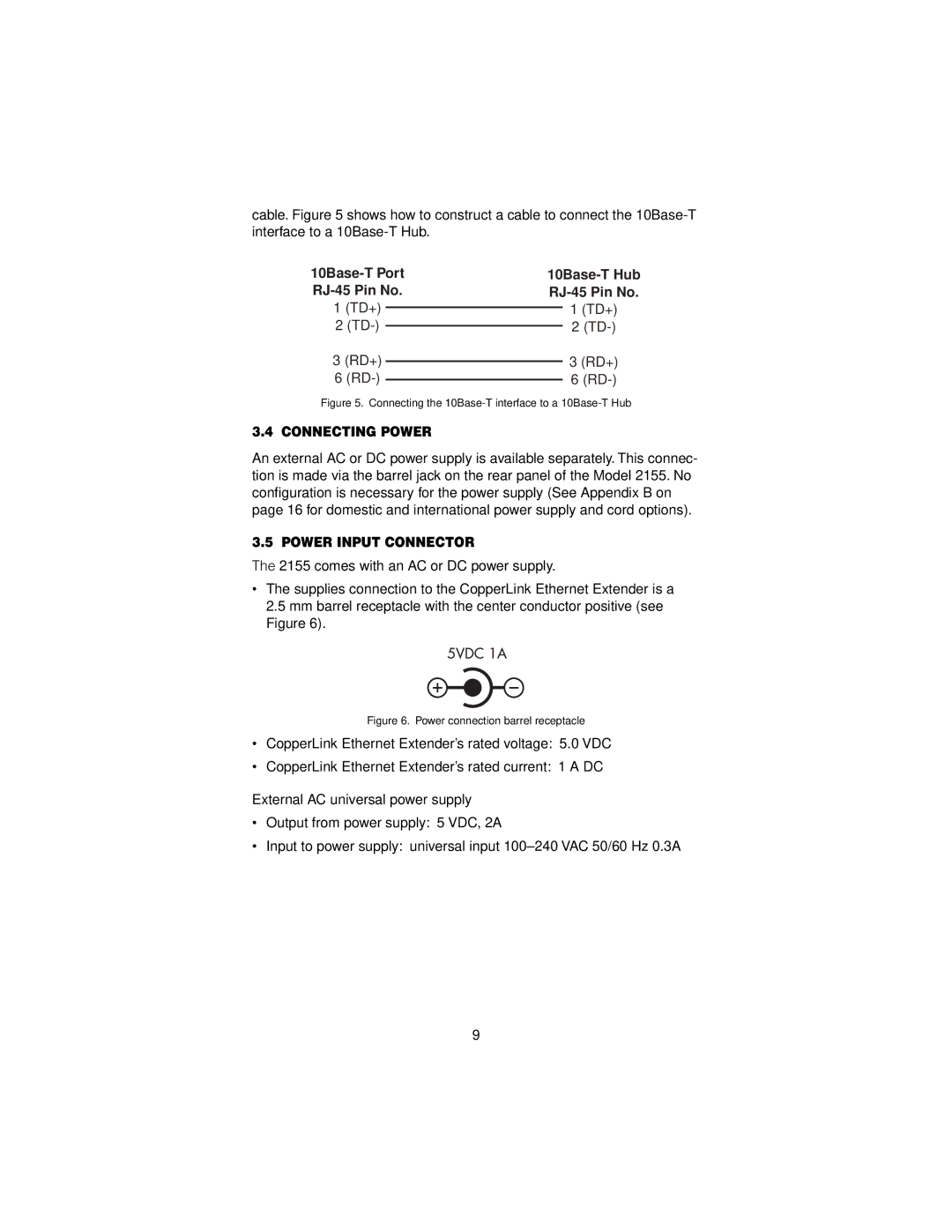
cable. Figure 5 shows how to construct a cable to connect the
| |||
1 (TD+) |
|
| 1 (TD+) |
|
| ||
2 |
|
| 2 |
|
| ||
3 (RD+) |
|
| 3 (RD+) |
|
| ||
6 |
|
| 6 |
|
| ||
Figure 5. Connecting the 10Base-T interface to a 10Base-T Hub
3.4 CONNECTING POWER
An external AC or DC power supply is available separately. This connec- tion is made via the barrel jack on the rear panel of the Model 2155. No configuration is necessary for the power supply (See Appendix B on page 16 for domestic and international power supply and cord options).
3.5 POWER INPUT CONNECTOR
The 2155 comes with an AC or DC power supply.
•The supplies connection to the CopperLink Ethernet Extender is a 2.5 mm barrel receptacle with the center conductor positive (see Figure 6).
Figure 6. Power connection barrel receptacle
•CopperLink Ethernet Extender’s rated voltage: 5.0 VDC
•CopperLink Ethernet Extender’s rated current: 1 A DC
External AC universal power supply
•Output from power supply: 5 VDC, 2A
•Input to power supply: universal input
9
