1.To function properly, two Ethernet Extenders must be connected together using twisted-pair, unconditioned, dry, metal wire, between 19 (0.9mm) and 26 AWG (0.4mm). Leased circuits that run through signal equalization equipment are not acceptable.
2.The Models 2155 are equipped with an RJ-45 interface. The Copper- Link interfaces are a two-wire interface. Observe the signal/pin rela- tionships on the CopperLink interface jack.
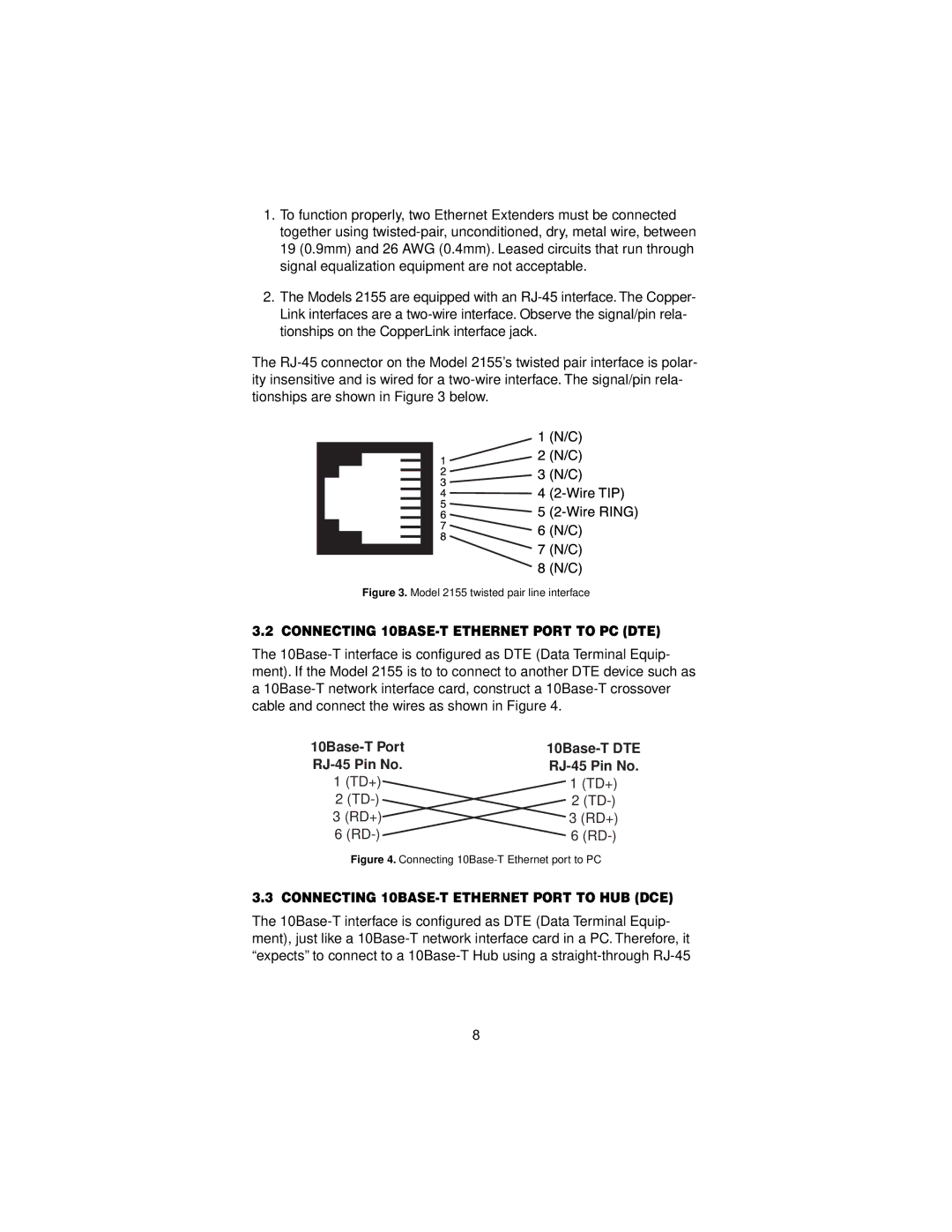
The RJ-45 connector on the Model 2155’s twisted pair interface is polar- ity insensitive and is wired for a two-wire interface. The signal/pin rela- tionships are shown in Figure 3 below.
Figure 3. Model 2155 twisted pair line interface
3.2 CONNECTING 10BASE-T ETHERNET PORT TO PC (DTE)
The 10Base-T interface is configured as DTE (Data Terminal Equip- ment). If the Model 2155 is to to connect to another DTE device such as a 10Base-T network interface card, construct a 10Base-T crossover cable and connect the wires as shown in Figure 4.
10Base-T Port | 10Base-T DTE |
RJ-45 Pin No. | RJ-45 Pin No. |
1 (TD+) | 1 (TD+) |
2 (TD-) | 2 (TD-) |
3 (RD+) | 3 (RD+) |
6 (RD-) | 6 (RD-) |
Figure 4. Connecting 10Base-T Ethernet port to PC
3.3 CONNECTING 10BASE-T ETHERNET PORT TO HUB (DCE)
The 10Base-T interface is configured as DTE (Data Terminal Equip- ment), just like a 10Base-T network interface card in a PC. Therefore, it “expects” to connect to a 10Base-T Hub using a straight-through RJ-45