3.0 INSTALLATION
Because the CopperLink Ethernet Extender requires no configuration, it can be installed quickly. Installation consists of the following:
•Connect the line interface between the units (refer to section 3.1, “Connecting the
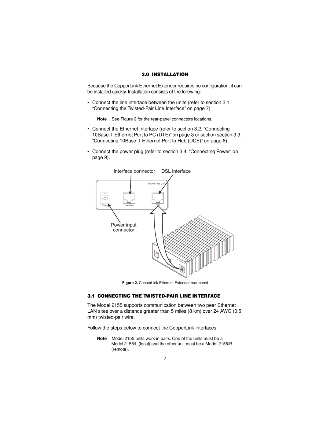
Note See Figure 2 for the
•Connect the Ethernet interface (refer to section 3.2, “Connecting
•Connect the power plug (refer to section 3.4, “Connecting Power” on page 9).
Interface connector DSL interface
ON
PowerOFF O | Interface |
Made in the USA
DSL |
Power input
connector
M d | l |
| . |
|
| |
Power | G | . |
| |||
|
| 1194E |
| 703/G |
|
|
|
|
|
| 704 |
| |
|
|
| Single | Test | Modes | |
|
|
|
| |||
|
|
|
|
| Mode | |
|
|
|
|
|
| |
|
|
|
|
| DSLFiber | |
- Quad
511EMade | in | the |
|
|
| ||
|
| USA | |
|
|
| |
G. |
|
|
|
703/G |
|
|
|
.704 |
|
| |
InterfaceModem | |||
Figure 2. CopperLink Ethernet Extender rear panel
3.1 CONNECTING THE TWISTED-PAIR LINE INTERFACE
The Model 2155 supports communication between two peer Ethernet LAN sites over a distance greater than 5 miles (8 km) over 24 AWG (0.5 mm)
Follow the steps below to connect the CopperLink interfaces.
Note Model 2155 units work in pairs. One of the units must be a Model 2155/L (local) and the other unit must be a Model 2155/R (remote).
7