3.0 CONFIGURATION
The Model 2715 features configuration capability via hardware switches or a software control port. This section describes all possible hardware and software switch configurations of the Model 2715.
3.1 DIP SWITCH CONFIGURATION
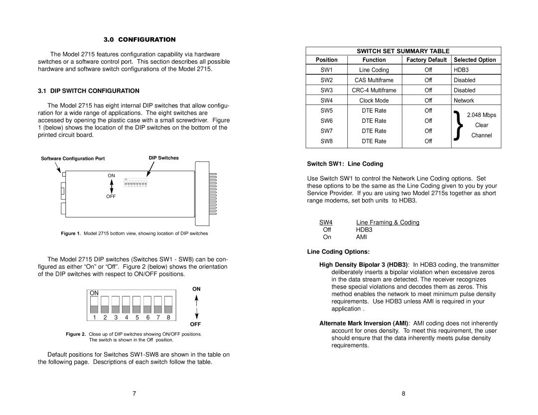
The Model 2715 has eight internal DIP switches that allow configu- ration for a wide range of applications. The eight switches are accessed by opening the plastic case with a small screwdriver. Figure 1 (below) shows the location of the DIP switches on the bottom of the printed circuit board.
Software Configuration Port | DIP Switches |
ON
OFF
Figure 1. Model 2715 bottom view, showing location of DIP switches
The Model 2715 DIP switches (Switches SW1 - SW8) can be con- figured as either “On” or “Off”. Figure 2 (below) shows the orientation of the DIP switches with respect to ON/OFF positions.
ON
OFF
Figure 2. Close up of DIP switches showing ON/OFF positions.
The switch is shown in the Off position.
Default positions for Switches
SWITCH SET SUMMARY TABLE
Position | Function | Factory Default | Selected Option | ||
SW1 | Line Coding | Off | HDB3 | ||
SW2 | CAS Multiframe | Off | Disabled | ||
|
|
|
|
| |
SW3 | Off | Disabled | |||
|
|
|
|
| |
SW4 | Clock Mode | Off | Network | ||
|
|
|
|
| |
SW5 | DTE Rate | Off |
|
| |
} | 2.048 Mbps | ||||
SW6 | DTE Rate | Off | |||
Clear | |||||
SW7 | DTE Rate | Off | |||
Channel | |||||
SW8 | DTE Rate | Off | |||
|
| ||||
|
|
|
|
| |
|
|
|
|
| |
Switch SW1: Line Coding
Use Switch SW1 to control the Network Line Coding options. Set these options to be the same as the Line Coding given to you by your Service Provider. If you are using two Model 2715s together as short range modems, set both units to HDB3.
SW4 | Line Framing & Coding |
Off | HDB3 |
On | AMI |
Line Coding Options:
High Density Bipolar 3 (HDB3): In HDB3 coding, the transmitter deliberately inserts a bipolar violation when excessive zeros in the data stream are detected. The receiver recognizes these special violations and decodes them as zeros. This method enables the network to meet minimum pulse density requirements. Use HDB3 unless AMI is required in your application .
Alternate Mark Inversion (AMI): AMI coding does not inherently account for ones density. To meet this requirement, the user should ensure that the data inherently meets pulse density requirements.
7 | 8 |
