Rapid Eye Software
Page
Revisions Issue Date
Page
Table of Contents
Unit Configuration Basics
System Administrator’s Guide
Pan, Tilt, and Zoom PTZ Setup
Enhancing Video for Security 103
129
Security for a Multi-Media System 161
201
Touring Many Sites 221
Figures
Page
System Administrator’s Guide
Tables
Admin Icon on the Windows Desktop 232
System Administrator’s Guide
Table of Contents
Administration of a Rapid Eye System
About Using a PC to Operate Rapid Eye Units
Start Here
Using a PC Installing Rapid Eye Software
About Using LocalView Onsite
For the Multi SA Only Admin and View Software
First Use Running Admin Software
Using View software for site maintenance
Customizing a Unit View Software
In-depth reference Configuration malfunctions
For Questions
Calling Honeywell
Road map
Last valid password
Multi-Media Site Name
Preparations
Site Setup Checklist
Naming / Renaming a Site
Four items
Site Naming Tips
After Dealing with a Site
Click Save and Close
Flexibility
Grouping Sites
To Create a Folder
To Assign a Site to a Folder
To assign a folder to a folder
To Rename a Folder
To Delete a Folder
Grouping Folders
Removing a Site
To Delete a Site
Mistakenly Deleting a Secured Site Definition
Multi-Media Site Connection Configuration
Types of Connection
Naming and viewing a connection
Selecting a Network or Dial-up Connection
Dial-up Connection to a Unit
Automatic Tag Added to a Connections Name
Setting a Dial-Up Connection
To Force a Long-distance Dial-up Using a Local Area Code
Area Code Irregular Use
Click Use Dial-up Networking as needed
Click Use Dial-up Networking
Should you plan to add an alarm station
Forcing a Local Dial-up Across Area Codes
Dial-up Technical Note
Offering Many Dial-Up Connections to the Same Unit
Using Network Access
Site Tab’s Report of Primary Connections
To Set a Network Connection
LocalView
Static network settings, default for Multi-Media unit
IP defaults used by Multi-Media units Point Address
Standalone Unit and a PC that Has a Network Card
IP Port
Network Address Translation
A nutshell
IP Addresses
See -5,p
Adjusting a Unit’s IP Settings for NAT
Network device mappings
Setting a Router’s Mappings
Updating a Units Connection
Dynamic Host Configuration Protocol
To Configure Dhcp Using Microsoft’s Server2000 or
Network administrator needs for using Dhcp with DNS
More about Dhcp
Choosing the Computer Name or a Static IP
IP Address box
Network without Dhcp
Primary connection
Setting up many connections is optional
Many Connections to a Unit
To Specify Dial-up and Network Connections
Planning to Connect to One Unit at a Time
RAS Server
What your network administrator needs
To Set a Connection to a RAS
Connection that behaves like dial-up
14. RAS Servers Telephone Number and PPP Information
Preparation
Using a RAS Server before Connecting to a Unit
RAS server may not be needed by your organization
Planning to connect to many units
Changing the Automatic Suffix in a Connections Name
About Admin’s naming convention for connections
Connections Report and Customization
Automatic Naming of Connections
Firewall Technical Note
Cascading Alarm Stations
Using the Update Site windows
To Sequence a Site’s Alarm Stations
Quickly Assigning a Site to Many Alarm Stations
Setting a Site to Not Report Alarms to a Specific Station
Customizing a Dial-Up Connection to an Alarm Station
To Cancel the Customization of a Telephone Number
To Customize the Dial-up Connection to an Alarm Station
Using a Maintenance Session
Unit Configuration Basics
Maintenance Session
Using View
Support for Older Models of Units
To Start a Maintenance Session
First Maintenance Session
Making a Site Operational
Site registration
Scheduling options
Crucial settings for reporting on video of events
Unit’s Time Zone and Clock
Security considerations
To Indicate the Time Zone of a Multi-Media Unit
Conflicting Time Zones
Time zone
Auto-synch statistics
Sntp Setting the Clock Automatically
Click Set Multi-Media Unit’s Clock
System Clock Manual Setting
Adjusting the Clock on a PC Running Rapid Eye Software
Using a PC’s Clock to Set a Unit’s Clock Manually
Correcting the Clock
Adjusting the Time on an Operational Unit
Securing a Site
Rebooting a Unit
Lack of reasons to reboot a Multi-Media unit
Automatic reboot of Multi-Media unit
Maintenance Topics
Maintenance Reference
Ending Maintenance
Using Apply
Maintenance Tasks
Feedback Box Reference
Automatic detection
Video Feed Setup
Cameras
Renaming a Camera
To Adjust All Cameras at Once
Adjusting a Video Feed
To Re-enable One Cameras Feed
To Re-enable All Newly Connected, Powered Cameras
Motion
Other Video Settings
Recording settings
Smoothing video
Screen area size of camera windows on a PC monitor
Recording Video Continuous Recording Settings
To Enable the Recording of a Video Feed
Making use of a Maintenance Session
Forecasting results
Customizing Settings for Recorded Video
Resolution Setting
Making settings
Frame Rate Setting
Quality Setting
To Duplicate Settings
Estimating Storage Capacity
Continuous Recording and Event Recording
Preparation contiguous connections
Optimizing Recorded Video
Automatic Maximization of DSP Performance
Rapid Eye Storage Estimator
Automatic display of Maximization tool
Enhanced Preview of Resolution
Making Optimized Resolution and Frame Rate Settings
Manual display of Maximization window
10. The Enhanced Preview Window
Resolution Tips
Comparing the Resolutions of Recorded Video
Security and Presence
12. Using Low Resolution, 160 x 120 Ntsc to Show Presence
Screen area size of camera windows on a PC monitor
Resolution Gauge for Retrieval Session
Camera Tips for Identification Quality and Resolution
Ntsc gauge
Continuous Recording and Event Recording
PAL gauge
Gauge in a Retrieval Session‡
Resolution Reference Recorded Video
Resolution
Comment
PC Monitor’s Refresh Rate
Customizing Windows for a PC Monitor’s Settings
Using Microsoft Windows
Using two monitors and running View software
Larger Monitors and Microsoft Windows
Environmental Interference for Video Feeds
Physical Compromise
Preventive measures
Serial Device Settings for PTZ
Pan, Tilt, and Zoom PTZ Setup
Video Tab Settings for PTZ
To Assign and Set a New PTZ Device
Acuix dome camera domes
To Enable a PTZ Camera
To Display the PTZ Dartboard Control
Using a PTZ Camera
Using the Dartboard Control
Toggling between Zonal Mode and Pull Mode
Click Zonal PTZ Control Mode
Pulling the Rubber-Band
Using Zonal Mode
Auto-iris
To Configure a Preset on a PTZ Camera
Programming a PTZ Dome Camera
Auto-focus
Programming a PTZ Preset
To Test a Preset
Kalatel domes
Behavior of PTZ After a Session Closes
PTZ and motion detection
Ultrak KD6i domes
Do not use the Return To Auto-Iris on Ultrak KD6i domes
PTZ and motion search
Constant panning and video archive
Ultrak KD6i dome restriction
RapidDome PTZ Tours
Support for RapidDome PTZ Features
RapidDome Preset Tour
RapidDome Mimic Tour
To Test a Mimic Tour on a RapidDome Camera
To Setup a Tour of Presets on a RapidDome Camera
Testing a Preset Tour on a RapidDome Camera
Privacy Zones for RapidDome
To Set a Privacy Zone
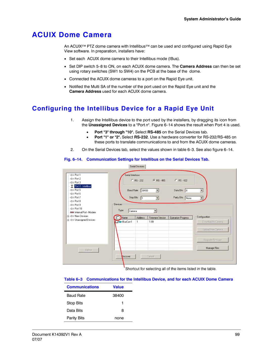
Acuix Dome Camera
Configuring the Intellibus Device for a Rapid Eye Unit
Discovery of Acuix Dome Cameras
To Configure an Acuix Dome Camera for PTZ Use
Backing Up an Acuix Configuration File to a PC
Commands in the Manage Files dialog box
Using LocalView
Downloading a Configuration File to an Acuix Dome Camera
Upgrading the Firmware of an Acuix Dome Camera
Identifying the Model of the Camera
Event Recording Configuration
Using Higher Settings for Video Recorded During an Event
Enhancing Video for Security
Event Recording on Demand, Using the Boost Button
Setting Lower Values for Continuous Recording
Scheduling Configuration
Automating Event Recording Events of Interest
Events of Interest examples
Alarms
Audio feeds
Data streams
Making Use of a Schedule
To Add a Schedule
Customizing a Schedule
Renaming cameras
Using a 15-minute Increment in a Schedule
Customizing the Default schedule
To Assign a Schedule to a Camera, or Group of Cameras
Alarms and Scheduling
To Rename a Schedule
To Delete a Schedule
Key facts
Holiday and Exception
To update a Name or a Type of holiday/exception
Adding Holidays and Exceptions
To correct a date
Trigger an Event of Interest
Event Recording for Video Scheduling a Response
Displaying the Response Panel Used for Making Rules
Checklist for Setting a Rule in the Response Schedule
Flexibility of checklist
Renaming a Rule
Rule Status Icons
Disabling a Response Rule
Alarm and Log to report a response
Managing the Response to a Rule
Assigning a Schedule to a Response Rule
Motion Detection
11. Motion Detection Configuration Detection scenarios
Masking movement that is of no concern
To Configure Motion Detection
Customizing Detection Masking
Example Masking an Area of the Video Feed
False Positives
Solutions
Video settings and motion detection
To Mask Part of a Video Feed from Motion Detection
Commands
Extra motion detection commands
Motion Detection Reference
Motion Search
Camera Sabotage Detection
Comparing Motion Detection and Motion Search
To Configure CSD
Calibration of CSD
Forty-eight seconds
Computing the Length of the Video Archive
Moved-type CSD Learning and Rearming Alarms
Estimate from a units statistics
Rapid Eye Storage Estimator
What to watch out for
Estimates
Audio
Number of Cameras, Audio
Video compression Quality
Scheduling Cameras
Frame Rate for Continuous Recording
Quality
Resolution
Using higher resolution
Pan, tilt, and zoom
Multi-Media Unit’s Storage Statistics
Using Higher Values When Recording Video
To Obtain a Unit’s Statistics
Storage Statistics for a Multi-Media Unit Label Meaning
Other statistics about the video archive
Configuring Other Hardware
Clearing Storage
Purpose
To change the name of a stream
Preventing Users from Clearing Storage
To clear a unit’s storage
Clearing a stream
Updating Security on a Multi-Media Unit
To Trace the Clearing of Storage
Security and unit availability considerations
Purpose System Log
System Files
To Download a File from a Multi-Media Unit
Removing a site after updating security
Double check that you are uploading the correct file
To upload a file to a Multi-Media unit
Multi-Media unit registration
System Tab in a Maintenance Session
Logging System Messages
System Monitor
Camera Signal Format
Making the Fault Relay Operational
Changing a Unit’s Network Settings
Default Network Communications Settings Box Value
LAN/WAN Communications
TCP Ports
Default System Values for a Multi-Media Unit
System Tab Default Values Box Group Name of Box / Button
Changing the Maximum Network Data Rate
Viewing/Changing Modem Settings
Modem settings
Serial Device Modem
To Set an External Modem
PPP IP Settings Reserved for Modem Connection
To Assign and Set a PTZ Device
PTZ device settings
Serial Device PTZ
Hardware Report
Public Display Monitor Using Monitor Output
External Hardware Control of a Public Display Monitor
Color bars
Using LocalView As an Additional Public Display Monitor
Adding a Customer Device That Sends Data to a Unit
Customer Data and Customer-Device Events
10. Some Devices can Be Searched for Data such as No Sale
Adding an Event Rule for a Data-recording Device
Search Rule and Regular Expressions Reference
Support for Protocol Interface Translators
NetPIT and PIT Devices
When listening
Multi Audio
Audio Hardware
Monitor and record
Using Multi Audio
Audio Interference
Audio with LocalView
Simultaneous Sessions From One Unit
Events
Audio broadcast
Simultaneous Use of Many Units by One Operator
Key Facts
Users
Before Creating User Accounts
Default User
User Management
Central User Management
Local User Management
Adding an Account, Using Admin and View
Setting a Unit to Central User Management
Account for accessing all units
Extras
Naming Restrictions
Updating an Account
Account for accessing one unit
Adding an Account in LocalView
User Groups
Granting Rights
Updating an Account in LocalView
To Customize the Rights in an Account
User Rights and Security
To Deny Access
Denying access to all Multi-Media units Admin
To Base Rights On Those of Another User
Local User Management
To Delete an Account Used Onsite, to Access LocalView
Denying access to LocalView, onsite
Removing a Users Account
Security outlook
Security for a Multi-Media System
Security Options
Securing the Multi System
Security Priorities Priority Action
Additional security for some installations
Security Priorities
From minimal security to maximum security
Features
Limiting the Use of Admin
To Limit Access to Admin Documentation
Password Guidelines
Passwords
Using text securely in Multi password boxes
Password Tip
Multi Database Security
SQL-Server Option
SQL-server Type Logon, Reserved for Multi Operators
A nutshell keeping unauthorized users out
System Password
Road Map to Setting the System Password
Always update security on all units
Do not use multiple Multi databases
Changing the System Password, Part 1 of 3 Using Admin
Changing System Password, Part 2 Multi-Media Units
Extra steps in some system password scenarios
Status Report
Removing a System Password
Changing System Password, Part 3 Updating Users
System password and security status
Remove From All Units
After Removing a System Password
Remove on One of Many Units
Replacing a Unit
System Password Extras
If the site cannot be accessed
To Replace a Unit when a System Password Is in Force
If a Used Unit Comes from Another Multi System
Last Valid Password
Last valid system password
Failure to run a Maintenance Session
Document K14392V1 Rev a 175 07/07
User password technical note
User Password
To Check if the Correct System Password Was Typed
Administrator Password
Basic security
To Set the Administrator Account’s Password
Password independence
Sharing the Administrator account
What you want to avoid
Rights of User Accounts
Guidelines
To View the Rights of a User and the Sites He may Access
Click Rights and site access are based on
Right to Use Admin
To Grant Access to Admin
Right to Use Maintenance
Right to Use View
Why limit the use of maintenance?
Why deny or limit access to a site?
Right to Access a Site
To Define an Account’s Access to Certain Sites
Why limit the use of View?
To Limit Use of Cameras Camera Partitioning
Limiting the Time that a Unit Can Be Used
Preventive measures a short checklist
High-Security Considerations
Physical compromise
Countermeasures
Security Happenstance
Situation Preventive and / or Last Resort Measures
Compromising video recording
Compromising and locking-out a Multi SA
Compromising response to an alarm
Setting an Event to Trigger an Alarm or to Be Logged
Events Defined
Preferences
To set alarms, two items must be part of the user’s account
Setting an Alarm
To Set an Event to Report an Alarm
Who can set alarms?
Logging an Event
Who can receive alarms?
Outside World
Event Reference
Tracing Events
Event Default Settings for Log and Alarm Source
Common sense
17. Search for Events Window
Event Session to Search the Log of Events
Results
To Set the Date of a Retrieval Using the Calendar Utility
System Failure
To Input Times and Dates
Alarm Notification Response Priority
Multi-Media Alarm Station
Rogue user scenarios
Denying Access
Best solution
PPP Connectivity
Outside hackers
Dealing with an open Maintenance Session
To Stop a Session on a Networked Multi-Media Unit
Stopping sessions on units that use modems
To Deny Access to a User of Your Multi System
Denying Access
Click Control Panel Double-clickAdd/Remove Programs
Using Windows Explorer to delete Multi files
Removing Multi-Media Software
Ineffective strategies for an unwanted user
Page
Multi-Media Alarm Stations
Where we are
Overview
Multi SA Needs
Checklist to Configure a Multi-Media Alarm Station
System Administrator Needs
Operator Needs
To reduce complexity further
Adding an Alarm Station Name and Reports
To reduce complexity add alarm station definitions
Identifying and Defining a Connection
PPP fields can be left blank
PPP Fields in an Alarm Station’s Definition
Scope
General case
To Setup a Network Connection to an Alarm Station
Network Connection to an Alarm Station
Mapping IP port in network’s router
Network Address Translation for Alarm Stations
Enable Use Network Address Translation
To Prepare a Multi-Media Unit for NAT, Using Admin
Microsoft Windows
Dial-up Connection to an Alarm Station
Preparing a Dial-up Connection to an Alarm Station
Modem
To Setup a Dial-up Connection to an Alarm Station
Entering Area Codes in Site and Alarm Station Definitions
Customizing a Dial-Up Connection to an Alarm Station
Irregular area code use
Toll-Free Numbers
To View Update Station to Call in Case of Alarms
To Delay the Speed of Dialing
To Use a Local Call Across Area Codes
Planning for a few international units
To Delay the Extension Suffix
International Dial-up
Telephone exchange at a Rapid Eye site
Alarm station for many international units
Creating extra alarm station definitions
To Change Long-distance Prefixes
RAS Connection to an Alarm Station
Customizing a RAS dial-up
To Setup a Connection to a RAS Server
Honeywell recommends using dialing same country
Tech note process of a dial-up callback
Disconnection Note
Making an Alarm Station Operational
Using More than one Alarm Station
Creating Extra Alarm Station Definitions for the same PC
To Trace the Unit Sending the Alarm
Removing an Alarm Station
Alarms from a De-listed or Unregistered Unit
To List Successful Alarm Callbacks after an Interruption
Precaution
To Set a Site to Not Report to a Specific Alarm Station
Preliminary Checklist
Touring Many Sites
Before defining a site tour
Adding a Site Tour
Default Amount of Time to Display a Unit During a Site Tour
To Change the Order of Sites in a Tour
Customizing a Tour
To Change the Time Spent at a Site, During a Tour
To Select Another Connection to a Site, During a Tour
Removing a Tour
Page
Alarm Log
Viewing the Log
To view the log
Selecting Log Items
Sorting the Log
Archiving the Log
To Print a List of Alarms
Filtering the Log
Printing the Log
Removing Log Items
To Archive Alarms
To Delete Alarms
Alarm Log Data Reference
MinAdmin
Multi Database
Database creation
Alternatives
Starting Admin
To Start Admin
Obtaining a Multi db
Contrasting Db Engines
Using the Default Multi Db
There may be other databases…
Using Another Db Converting
Converting a Multi database from SQL to Access
To Use Another Multi Db
Using the Admin Logon window to create a database
Creating a Multi Db
Impact on View
Naming Restriction
To Create an Empty, MS-Access-Compatible Multi Db
SQL-Server Template
An Empty Multi Database Using Microsoft SQL-Server
Using Admin to Create a SQL-compatible Multi Database
SQL-Server
Db Based On Another
To Make a Copy of a Multi Db
Similarities
File name of a local db is userid.mdb
Multi Db MinAdmin
Renaming a Multi Db
For making a copy of a db is not obvious
Purpose of a local database
Upgrades from v4 to v5 are automatic
Upgrading a Multi db
Upgrading a Local Database
Examples
Producing a Local Database
To Make a Local Database
Obtaining a local database, not connected to Multi db
First use exception
View Setting the Db
For routine use of Admin
Logging On
Local Multi database
To Set a Multi Db for View
Refreshing a Local Database
For routine use of View
Protecting the Multi db
Deleting a Database
To Refresh a Local Database while Running View
Cannot Open Db
Page
Index
Page
System Administrator’s Guide
Page
Parameters system password
Page
System Administrator’s Guide
Page
Page
Page
Page
Page
Page
Document K14392V1 Rev a 07/07