| 17 | 18 | 27 | 28 | |||
|
|
|
|
|
| BACK PANEL |
|
lANDBY POWER | ON | ON |
|
|
|
| |
0 | 0 |
|
|
| |||
|
|
|
|
|
| ||
|
| m |
|
|
| ||
PEAVE” ELECTRONICS CDRP | S T A N D B Y P O W E R |
|
|
| |||
PATENT PENDlNG |
|
|
|
| |||
|
|
|
|
| |||
|
|
|
|
|
|
|
|
19
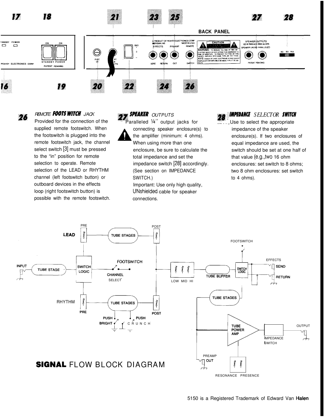
26 REMOTE FOOTS WITCH JACK Provided for the connection of the supplied remote footswitch. When the footswitch is plugged into the remote footswitch jack, the channel select switch [3] must be pressed to the “in” position for remote selection to operate. Remote selection of the LEAD or RHYTHM channel (left footswitch button) or outboard devices in the effects loop (right footswitch button) is possible with the remote footswitch.
sr SNAKER O U T P U T S | 28 : f IMPiEDAUCE SELECTOR SW/TCH |
; 1. Paralleled VV’ output jacks for | ..* |
.,... . .I’.,, Use to select the appropriate | |
connecting speaker enclosure(s) to | impedance of the speaker |
the amplifier (minimum: 4 ohms). | enclosure(s). If two enclosures of |
AWhen using more than one | equal impedance are used, the |
enclosure, be sure to calculate the | switch should be set at one half of |
total impedance and set the | that value (e.g.,two 16 ohm |
impedance switch [28] accordingly. | enclosures: set switch to 8 ohms; |
(See section on IMPEDANCE | two 8 ohm enclosures: set switch |
SWITCH.) | to 4 ohms). |
Important: Use only high quality, |
|
UNshielded cable for speaker |
|
connections. |
|
PREPOST
SELECT | LOW MID HI |
|
RHYTHM
BRIGHT1 1 C R U N C H
- -
T 1
SIGNAL FLOW BLOCK DIAGRAM
FOOTSWITCH
EFFECTS
I
OUTPUT
IMPEDANCE
SWITCH
PREAMP
t1
RESONANCE PRESENCE
5150 is a Registered Trademark of Edward Van Halen