Series
Table of Contents
Errors in Writable Character and PC Command Save Modes
Commands for System Administrator
195
196
205
199
208
210
Sdram
TCP/IP
Pcmcia
MF81M1-GBDAT01 D0H 1CH
EF-1M-TB AA D0H 1CH
EF-4M-TB CC
B0H
Interface
Page
Page
Input/Output Signals Printer
RTS CTS DSR DTR
RTS
CTS DSR
Interface Circuit Input Circuit SN75189 or equivalent
Output Circuit SN75188 or equivalent
RTS DTR
Parallel Interface
57RE-40360-73B or equivalent
DDK
Cable Amp. Japan Or equivalent
57E-30360 or equivalent
Chassis GND
NInit NFault NDataAvail NSelectIn IEEE1284 Active
Page
Page
Page
Page
Host → Printer
NStrobe Host → Printer
Busy Host ← Printer NAck
10 sec
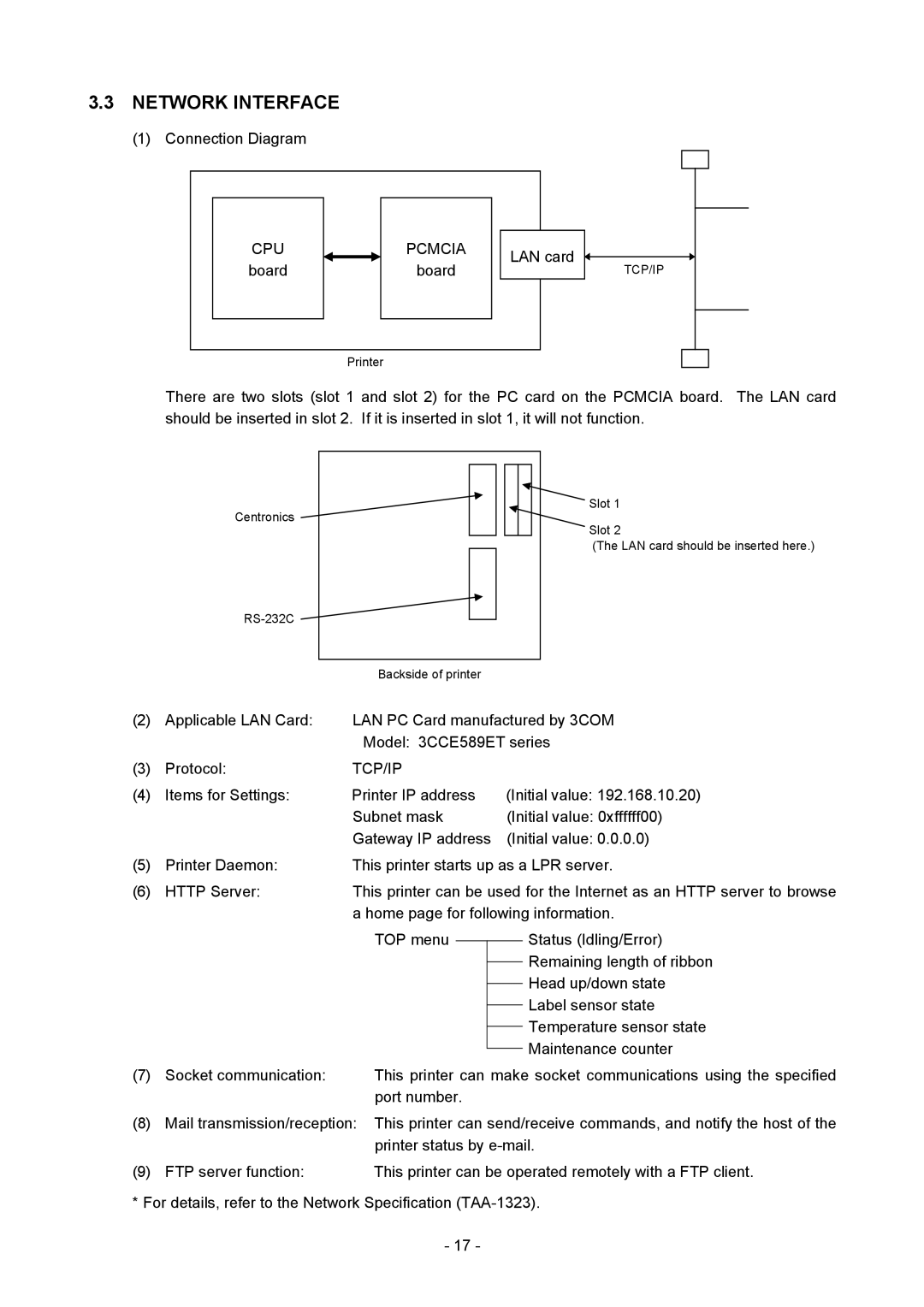
Connection Diagram
CPU Pcmcia
Board
None Even ODD
LATIN9
English German French Dutch Spanish Japanese Italian
TYPE1 TYPE2
OFF
Centronics ACK/BUSY timing setting
Hour
XON/XOFF + READY/BUSY
None
READY/BUSY DTR
Feed
Online Mode Functions
Transmission Sequence
Page
Label Issue Operation
Page
Command & Data
Format of Interface command
ESC
NUL
Commands for Creating Application
Commands for System Administrator
Label Size Set Command ESC D
Commands for Creating Application
Tags
Printing direction Printing top first Setting range
Print direction Printing bottom first
Labels Tags
Model 850 Method
Cut issue
Thermal head width 216.8 mm
Label
Page
Fanfold paper
Examples Labels Tags
Position Fine Adjust Command ESC AX
+3.0 mm
First print position home position after back feed
±9.9 mm
±50.0 mm
Strip issue for auto labeler
Examples Cut issue
ESC AX +020, +035, +10 LF NUL
ESC T21C40 LF NUL
Print Density Fine Adjust Command ESC AY
Ribbon Motor Drive Voltage Fine Adjust Command ESC RM
Image Buffer Clear Command ESC C
Clear Area Command ESC XR
Origin 0 Start point
Line Format Command ESC LC
Line Horizontal line In the case of Y2 Y1 =
Vertical line In the case of X2 X1 =
Slant line a X 2 X 1 ≤ Y 2 Y Slant line B X 2 X 1 Y 2 Y
Radius of rounded corners ≠
Page
Origin 0
Bit Map Font Format Command ESC PC
Prestige Elite Bold Point Courier Medium
OCR-A
OCR-B
Page
Page
Sample
OCR-A OCR-B
Relationship between drawing coordinates and magnification
180 270 Selection of character attribution
Rotational angles of a character and character string
Black characters Reverse characters
Boxed characters
INC/DEC
Bold character designation
A2A0A INC/DEC
A0A0A
A2A0A
A0A1A
Abcd
Page
Page
C D
Origin 0 Effective print area 55.0 mm 20.0 mm 65.0 mm
Outline Font Format Command ESC PV
Page
Page
Page
180 270
Backing paper Origin Label Paper
Type of font TEC FONT1 Helvetica bold
Character width and character height
Page
Page
180 270 Selection of character attribution Black characters
U a l s p a c e
Abcd
Page
Page
C D
ESC XS I, 0002, 0002C4000 LF$ NUL$
ESC RV S LF 001 LF NUL
KIX Code
Bar Code Format Command ESC XB
CODE93
UPC-A
CODE128 Pseudo
WPC
CODE128 Pseudo UCC/EAN128
Postnet
Page
CODE39
MSI
ITF
Page
Page
Page
Page
Page
Parameter No. of columns No. of rows
Page
Page
Backing paper Origin Label
UPC-A + 2 digits
KIX code MaxiCode
Postnet RM4SCC
JAN, EAN, UPC CODE93
Type of bar code Narrow Wide Character-to-character
MSI ITF CODE39 NW7
Case of QR code
Postal code
Bar code height
Page
INC/DEC
No. of zeros to be suppressed
102
ECC50
ECC0
ECC80
ECC0 ECC50 ECC80
Row Col
ECC200
Page
Cell width
Page
Page
15.0 55.0 20.0 mm 83.0 mm 15.0 mm
ESC RB S LF 001 LF NUL
ESC XB01 0200, 0125, P, 04, 02, 03, 0, 0010 LF NUL
ESC XB02 0830, 0550, Q, 08, 03, 05, 3 LF NUL
ESC RB02 Data Matrix LF NUL
Bit Map Font Data Command ESC RC
Sample
115
Outline Font Data Command ESC RV
Origin 0 Effective print area 12.5 mm
ESC C LF NUL
Bar Code Data Command ESC RB
Or 11 digits
Royal Mail 4 State Customer Code 12 digits
ECC0 ECC50
ECC200
Sets the security level automatically
Parameter No. of columns No. of rows
Page
Page
Page
Transfer code for QR code
128
12.5 mm 15.0 mm 55.0 mm 20.0 mm 83.0 mm
ESC C LF NUL
ESC XB02 0830, 0550, Q, 08, 04, 05, 3 LF NUL
Issue Command ESC XS
Page
Page
Idling
Issue mode Batch mode cut interval
End of printing the 1st label a
Feeds the 1st label a to the cut position
Reverse feed to the home position
Idling during the forward feed standby
Mm automatic forward feed
After 1 second
End of printing the 3rd label C
Tags 138
Tags Printing top first
139
Labels Tags Mirror printing top first
M p l e
Stop position after feeding one label
Paper is moved in the above state
External equipment
Feed Command ESC T
Page
Feed mode Batch Non-cut
Or E Strip mode for auto labeler
M p l e
ESC IB LF NUL
Eject Command ESC IB
Forward/Reverse Feed Command ESC U1, ESC U2
AA a AAA
Storage Area Allocate Command ESC XF
Page
Memory Card Format Command ESC J1, ESC JA
20 2-byte Writable Character Code Range Command ESC XE
Bit Map Writable Character Command ESC XD, ESC XA
Page
Page
= Writable character
Hex. mode
Writable character set 01 to 40, 51 to
158
Page
Writable character set 41 16×16 dots
Writable character set 42 24×24 dots
Writable character set 43 32×32 dots
Writable character set 44 48×48 dots
Page
Examples Writable character set Writable character code 70H
Graphic Command ESC SG
Graphic
Graphic width 19 dots
Not present Present
When Topix compression mode is selected
Data after being compressed Line No Graphic data
Page
24.0 mm Origin
Topix compression mode
Save Start Command ESC XO, ECS
175
ESC XP LF NUL
Save Terminate Command ESC XP
Saved Data Call Command ESC XQ, ESC XT
Head Broken Dots Check Command ESC HD
Message Display Command ESC XJ
Examples Load paper Feed one label. e Issue 4 labels
ESC WR LF NUL
Reset Command ESC WR
ESC WS LF NUL
Status Request Command ESC WS
Version Information Acquire Command ESC WV
ATA Card Information Acquire Command ESC WI
Stored PC command save file name
Character Storage
IP Address Set Command ESC IP
Socket Communication Port Set Command ESC is
Parameter Set Command ESC Z2
None Even
ODD 189
English German French Dutch Spanish Japanese Italian
Web printer function is enabled
Web printer function is disabled
Fine Adjustment Value Set Command ESC Z2
Page
Batch Reset Command ESC Z0 zero
Control Code Selection
Error Processing
Page
Errors in Writable Character and PC Command Save Modes
Status Format
Functions
Detail Status
An Eeprom for back up cannot be Read/written properly
LCD Message Printer Status
Compatible Mode
System Error
Nibble Mode Status Format
XxH
3XH 0DH 0AH
Online mode Yes PCL emulation mode
Online mode Yes
Online mode Yes Keyboard KB-80 is Connected
Online mode Yes Communicating
An Eeprom for back-up Cannot be read/written Properly
XR0200,0300,045
Example 2 ESC T20 E40 LF NUL Command error LCD display
English
LCD Messages in Different Languages
209
Italian
Character Code Table
Page
Page
Page
Page
Page
Page
Page
Page
Page
Page
? O o
OCR-ABit map font type S PC-850, PC-857
Page
PC-1252, PC-1254
Page
Page
Page
Page
Page
Page
Page
Page
Page
Page
Page
Page
Page
PC-852 ´´o
Page
Page
Page
Page
Page
PC-850 243
TrueType Font
PC-852 PC-857 244
PC-851 PC-855 245
PC-1250 PC-1251 246
PC-1252 10 PC-1253 247
11 PC-1254 12 PC-1257 248
LATIN9 Arabic 249
WPC JAN, EAN, UPC
BAR Code Table
NW-7 CODE93 Transfer code Drawing code 251
CODE128 Transfer code
Start Code a Start Code B Start Code C
Drawing code Value Code Table 252
102 FNC1 FNC1 FNC1
FNC4
How to send control code data
00H 3EH, 40H
01H 3EH, 41H
NUL
NUL
257
2 3 4 5 6, K Kanji data, B 0 0 1 0 a E o B C
ABC
Postnet RM4SCC KIX Code
Postal code Customer bar code
BEL
260
SOH
Modulus 10 check
Auto affix of modulus
262
Auto affix of modulus 10 + price C/D 4 digits
Type of Bar Code JAN13, EAN13 No affix
Auto affix of modulus 10 + price C/D 5 digits
263
Type of Bar Code UPC-A No affix
265
Type of Bar Code UPC-E No affix
266
Type of Bar Code JAN8 +2 digits, EAN8 + 2 digits No affix
267
Type of Bar Code JAN8 +5 digits, EAN8 + 5 digits No affix
Type of Bar Code JAN13 +2 digits, EAN13 + 2 digits No affix
269
Type of Bar Code JAN13 +5 digits, EAN13 + 5 digits No affix
Type of Bar Code UPC-A + 2 digits No affix
Type of Bar Code UPC-A + 5 digits No affix
272
Type of Bar Code UPC-E + 2 digits No affix
Type of Bar Code UPC-E + 5 digits No affix
IBM modulus 10 check
Type of Bar Code MSI No affix
Auto affix of IBM modulus
IBM modulus 10 + Auto affix of IBM modulus
Type of Bar Code Interleaved 2 No affix
Auto affix of DBP modulus
275
Modulus check character check
Type of Bar Code Industrial 2 No affix
Auto affix of modulus check character
276
Modulus 43 check
Type of Bar Code CODE39 Standard No affix
Type of Bar Code NW7 No affix C/D check Auto affix
Type of Bar Code CODE39 Full Ascii No affix
279
280
Type of Bar Code CODE93 No affix C/D check Auto affix of C/D
Type of Bar Code RM4SCC Auto affix of dedicated C/D
Type of Bar Code Postnet Auto affix of dedicated C/D
Type of Bar Code KIX Code No affix
281
CC7
Automatic Adding of START/STOP Code
NW7