(13) Link field No.
Notes
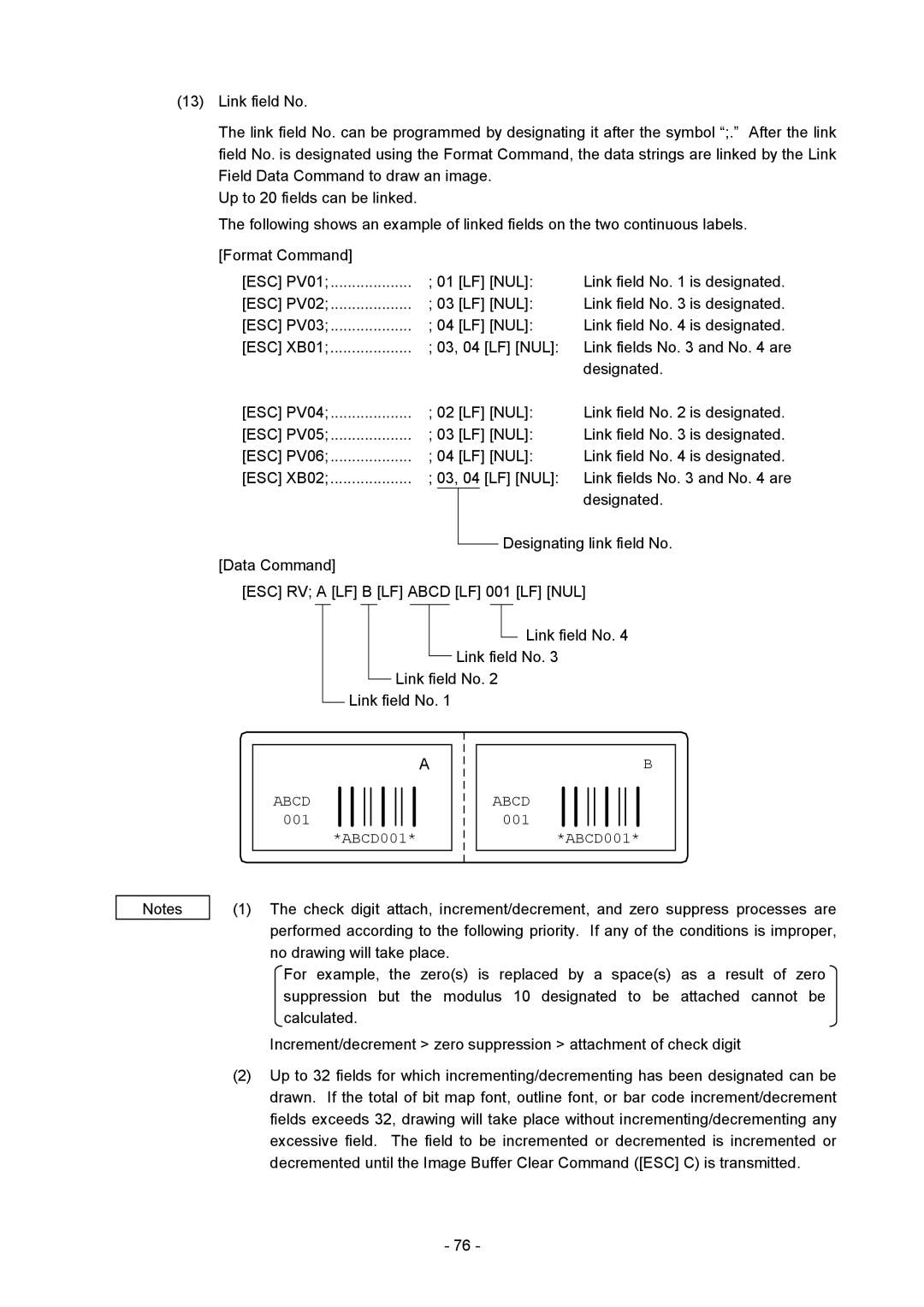
The link field No. can be programmed by designating it after the symbol “;.” After the link field No. is designated using the Format Command, the data strings are linked by the Link Field Data Command to draw an image.
Up to 20 fields can be linked.
The following shows an example of linked fields on the two continuous labels.
[Format Command] |
|
|
|
|
|
|
[ESC] PV01; | ; 01 [LF] [NUL]: | Link field No. 1 is designated. | ||||
[ESC] PV02; | ; 03 [LF] [NUL]: | Link field No. 3 is designated. | ||||
[ESC] PV03; | ; 04 [LF] [NUL]: | Link field No. 4 is designated. | ||||
[ESC] XB01; | ; 03, 04 [LF] [NUL]: | Link fields No. 3 and No. 4 are | ||||
|
|
|
|
|
| designated. |
[ESC] PV04; | ; 02 [LF] [NUL]: | Link field No. 2 is designated. | ||||
[ESC] PV05; | ; 03 [LF] [NUL]: | Link field No. 3 is designated. | ||||
[ESC] PV06; | ; 04 [LF] [NUL]: | Link field No. 4 is designated. | ||||
[ESC] XB02; | ; 03, 04 [LF] [NUL]: | Link fields No. 3 and No. 4 are | ||||
|
|
|
|
|
| designated. |
[Data Command] |
|
|
|
| Designating link field No. | |
|
|
|
| |||
|
|
|
|
|
| |
[ESC] RV; A [LF] B [LF] ABCD [LF] 001 [LF] [NUL]
![]() Link field No. 4 Link field No. 3
Link field No. 4 Link field No. 3
Link field No. 2 Link field No. 1
|
|
|
|
|
|
|
|
|
|
|
|
|
|
|
|
|
|
|
|
|
|
|
|
|
|
|
|
|
|
|
|
|
|
|
| A |
|
|
|
|
|
|
|
|
|
|
|
|
| B |
|
|
|
|
|
|
|
|
|
|
|
|
|
|
|
|
|
|
|
|
|
|
|
|
| ||
|
|
|
|
|
|
|
|
|
|
|
|
|
|
|
|
|
|
|
|
|
|
|
| ||
|
|
|
|
|
|
|
|
|
|
|
|
|
|
|
|
|
|
|
|
|
|
|
|
|
|
|
|
|
|
|
|
|
|
|
|
|
|
|
|
|
|
|
|
|
|
|
|
|
|
|
|
| ABCD |
|
|
|
|
|
|
|
|
|
|
|
|
| ABCD |
|
|
|
|
|
|
|
|
|
|
|
|
|
|
|
|
|
|
|
|
|
|
|
|
|
|
|
|
|
|
|
|
|
| ||
| 001 |
|
|
|
|
|
|
|
|
|
|
|
|
| 001 |
|
|
|
|
|
|
|
|
|
|
|
|
|
|
|
|
|
|
|
|
|
|
|
|
|
|
|
|
|
|
|
|
|
| ||
|
|
|
|
|
|
|
|
|
|
|
|
|
|
|
|
|
|
|
|
|
|
|
| ||
|
| *ABCD001* |
|
|
|
| *ABCD001* | ||||||||||||||||||
|
|
|
|
|
| ||||||||||||||||||||
|
|
| |||||||||||||||||||||||
|
|
|
|
|
| ||||||||||||||||||||
|
|
|
|
|
| ||||||||||||||||||||
|
|
|
|
|
|
|
|
|
|
|
|
|
|
|
|
|
|
|
|
|
|
|
|
|
|
(1)The check digit attach, increment/decrement, and zero suppress processes are performed according to the following priority. If any of the conditions is improper, no drawing will take place.
For example, the zero(s) is replaced by a space(s) as a result of zero suppression but the modulus 10 designated to be attached cannot be calculated.
Increment/decrement > zero suppression > attachment of check digit
(2)Up to 32 fields for which incrementing/decrementing has been designated can be drawn. If the total of bit map font, outline font, or bar code increment/decrement fields exceeds 32, drawing will take place without incrementing/decrementing any excessive field. The field to be incremented or decremented is incremented or decremented until the Image Buffer Clear Command ([ESC] C) is transmitted.
- 76 -
