21.MUTEBUS
The mutebus is a control port that when shorted to ground will mute all channels that are assigned to the mutebus approximately 45dB. The channels to be muted must be assigned to the mutebus using the internal switch marked OFF/MBUS. See INTERNAL PANEL FEATURES, page 4 and diagram page 7.
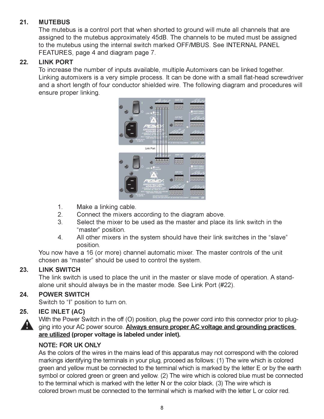
22.LINK PORT
To increase the number of inputs available, multiple Automixers can be linked together. Linking automixers is a very simple process. It can be done with a small
Link Port |
1.Make a linking cable.
2.Connect the mixers according to the diagram above.
3.Select the mixer to be used as the master and place its link switch in the ÒmasterÓ position.
4.All other mixers in the system should have their link switches in the ÒslaveÓ position.
You now have a 16 (or more) channel automatic mixer. The master controls of the unit chosen as ÒmasterÓ should be used to control the system.
23.LINK SWITCH
The link switch is used to place the unit in the master or slave mode of operation. A stand- alone unit should always be in the master mode. See Link Port (#22).
24.POWER SWITCH
Switch to ÒIÓ position to turn on.
25.IEC INLET (AC)
With the Power Switch in the off (O) position, plug the power cord into this connector prior to plug-
ging into your AC power source. Always ensure proper AC voltage and grounding practices are utilized (proper voltage is labeled under inlet).
NOTE: FOR UK ONLY
As the colors of the wires in the mains lead of this apparatus may not correspond with the colored markings identifying the terminals in your plug, proceed as follows: (1) The wire which is colored green and yellow must be connected to the terminal which is marked by the letter E or by the earth symbol or colored green or green and yellow. (2) The wire which is colored blue must be connected to the terminal which is marked with the letter N or the color black. (3) The wire which is
colored brown must be connected to the terminal which is marked with the letter L or color red.
8